Co-extrusion die head for extruding profiled bars with co-extrusion surface

A technology of co-extrusion die and profile material, applied in the field of co-extrusion die, can solve the problem of uneven co-extrusion layer and achieve the effect of uniform co-extrusion layer and uniform flow

Inactive Publication Date: 2011-04-06
TONGLING TRINITY TECH
View PDF7 Cites 9 Cited by
  • Summary
  • Abstract
  • Description
  • Claims
  • Application Information

AI Technical Summary

Problems solved by technology

[0003] The purpose of the present invention is to solve the problem of uneven co-extrusion layer caused by the inconsistent flow rate of the co-extrusion channel, and to provide a co-extrusion die head for extruding profiled materials with a co-extrusion surface, so that the material flow in the extrusion channel is uniform, Ability to obtain profiles with uniform co-extruded layers

Method used


Image

  • Co-extrusion die head for extruding profiled bars with co-extrusion surface
  • Co-extrusion die head for extruding profiled bars with co-extrusion surface
  • Co-extrusion die head for extruding profiled bars with co-extrusion surface

Examples


Embodiment Construction

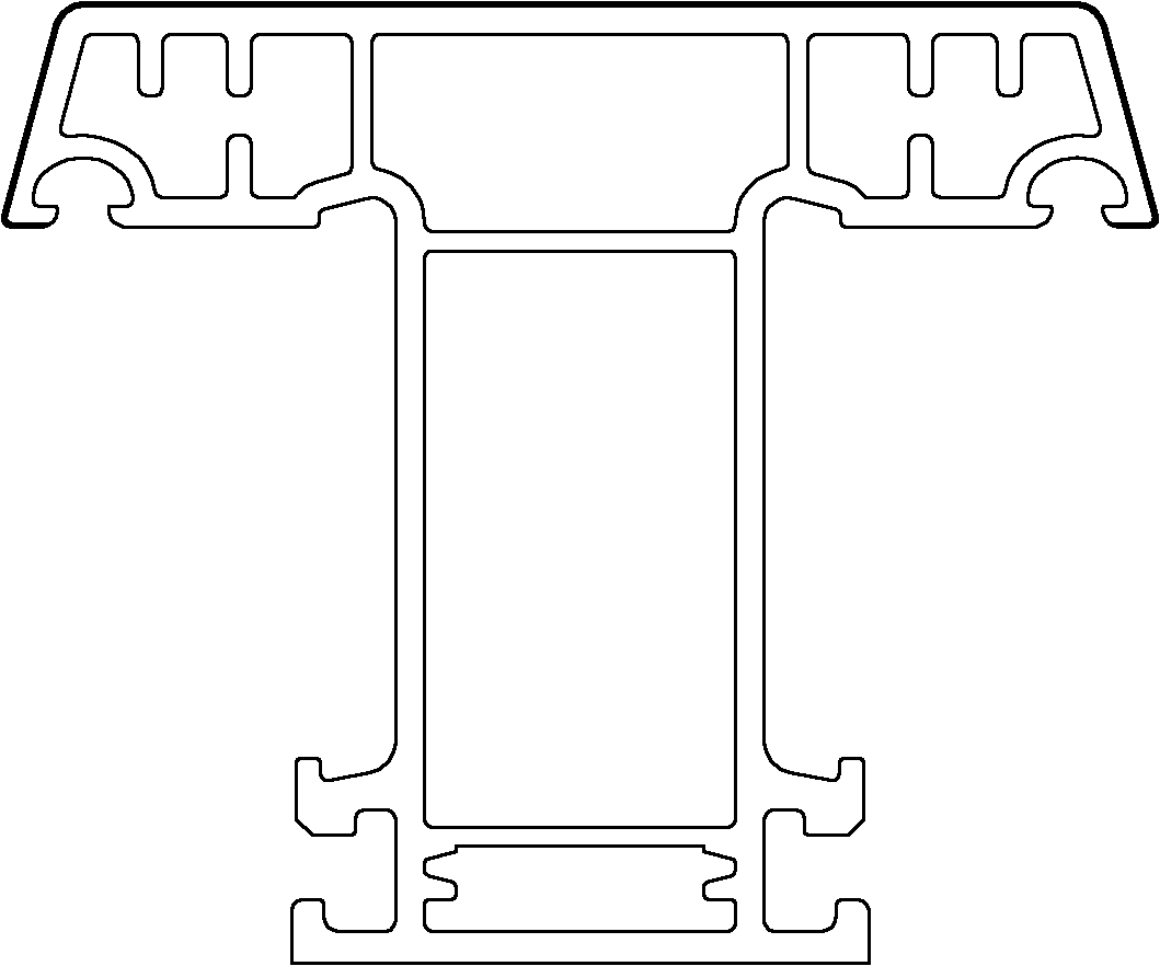
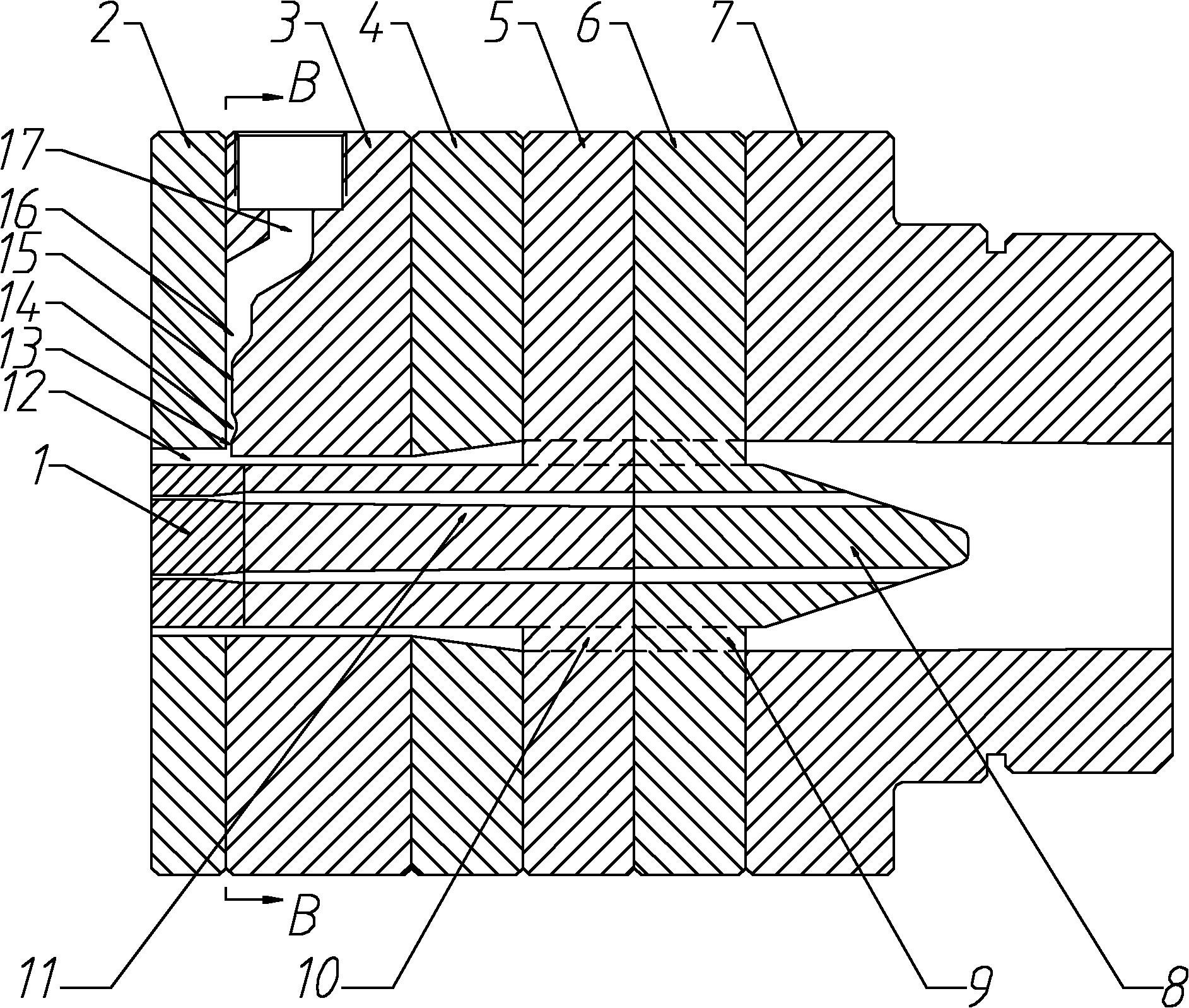
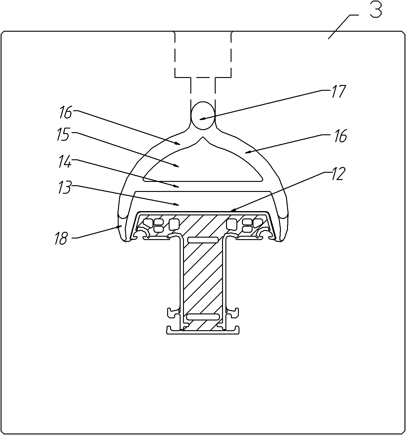
[0009] Co-extrusion die head of the present invention such as figure 2 and image 3 As shown, it includes machine neck 7, transition plate 6, bracket plate 5, compression plate 4, preformed plate 3, forming plate 2 and insert 1, splitter cone 8 is integrated with transition plate 6 through connecting rib 9, and core 11 is integrated with the bracket plate 5 through the connecting rib 10, and the insert 1 is fixed on the core 11 by screws. The co-extrusion channel is set on the preformed plate, including the main channel 17, the fan-shaped runner 16, the guide groove 18 and the co-extrusion parallel section 13, and the fan-shaped runner 16 is provided with a blocking island 15 protruding into the flow channel , so that between the blocking island 15 and the co-extrusion parallel section 13, a reservoir 14 with a section wider than that of the co-extrusion parallel section 13 is formed. The co-extrusion material is extruded into the sub-runner 16 through the main channel 17, ...


PUM


Abstract

The invention relates to a co-extrusion die head for extruding profiled bars with a co-extrusion surface, comprising a machine neck, a transition plate, a supporting plate, a compressing plate, a pre-forming plate, a forming plate and an embedded lump; the pre-forming plate is provided with a co-extrusion flow passage; the co-extrusion flow passage comprises a main flow passage, a sector sub-flowpassage expanded towards the two sides of the die cavity co-extrusion surface, and co-extrusion parallel sections leading to the die cavity co-extrusion surface; the sector sub-flow passage is internally provided with a flow-choking piece protruded towards the inner part of the flow passage so as to form a material storage pool in which the section is wider than the co-extrusion parallel sectionsbetween the flow-choking piece and the co-extrusion parallel sections. The flow-choking piece can initially split the co-extrusion materials into flows, and the material storage pool can split the co-extrusion materials into flows again after the co-extrusion materials are combined so as to form section bars with uniform co-extrusion layers.

Description

technical field [0001] The invention relates to a co-extrusion die head for extruding a profiled material with a co-extrusion surface. Background technique [0002] For plastic profiles that require colored material coating on the outer surface, that is, colored co-extruded profiles, such as figure 1 The upper surface of the profile shown is a colored co-extrusion surface, and the co-extrusion flow channel is usually set on the preformed plate of the co-extrusion die head. The co-extrusion parallel section leading to the co-extrusion surface of the cavity, the co-extrusion material enters the co-extrusion surface of the cavity through the main channel, the runner, and the co-extrusion parallel section to meet the base material. The co-extrusion material is heated and plasticized by the co-extrusion machine, then extruded through the co-extrusion port of the die head into the co-extrusion channel, further divided and plasticized in the co-extrusion channel, and extruded from...

Claims


Application Information

Patent Timeline
Patent Type & Authority Applications(China)
IPC IPC(8): B29C47/12B29C48/30
Inventor 张家权张金银吴翠红徐小停钱成建孙晓峰
Owner TONGLING TRINITY TECH
Why Eureka
Try Eureka