Splayed cylinder mould sand barrier and construction structure thereof

A figure-eight, mesh cage technology, applied in the engineering field, can solve the problems of large amount of consumables, semi-concealed sand barriers that can only fix sand, and high cost

Inactive Publication Date: 2011-04-06
娄志平
View PDF1 Cites 7 Cited by
  • Summary
  • Abstract
  • Description
  • Claims
  • Application Information

AI Technical Summary

Problems solved by technology

The existing mechanical sand barriers are divided into three categories: one is flat sand barriers, the other is semi-concealed sand barriers, and the other is vertical sand barriers; Laying barriers all over the desert requires a large amount of materials and high cost, so it cannot be used on a large scale in sand control projects, and flat sand barriers and semi-concealed sand barriers can only fix sand and cannot intercept desert quicksand; the existing Due to technical reasons, the vertical sand barrier can only be used as a substitute for shrubs, and the sand blocking function only stays as if a row of bushes has been planted. The reason is that the existing technology cannot construct the vertical sand barrier to the top of the dune. On the sand ridge line, sand dunes cannot be used as sand barriers, because on the sand ridge line, the stability of the vertical sand barrier becomes a big problem, and the bottom will soon be swept away by the wind and fall down; the current vertical sand barrier In order to reduce wind resistance and avoid being buried by quicksand, the porosity of sand barriers is mostly greater than 40%. The method of allowing quicksand to pass through the vertical sand barrier and then stay there is adopted. When the quicksand moves to a distance 20 times the height of the sand barrier, the sand barrier will If the function of retaining them is lost, if there is no longer a sand barrier, the quicksand can drive straight in. If the construction continues one by one, not only the quicksand is still out of control, but the cost is also high

Method used


Image

  • Splayed cylinder mould sand barrier and construction structure thereof
  • Splayed cylinder mould sand barrier and construction structure thereof
  • Splayed cylinder mould sand barrier and construction structure thereof

Examples


Embodiment Construction

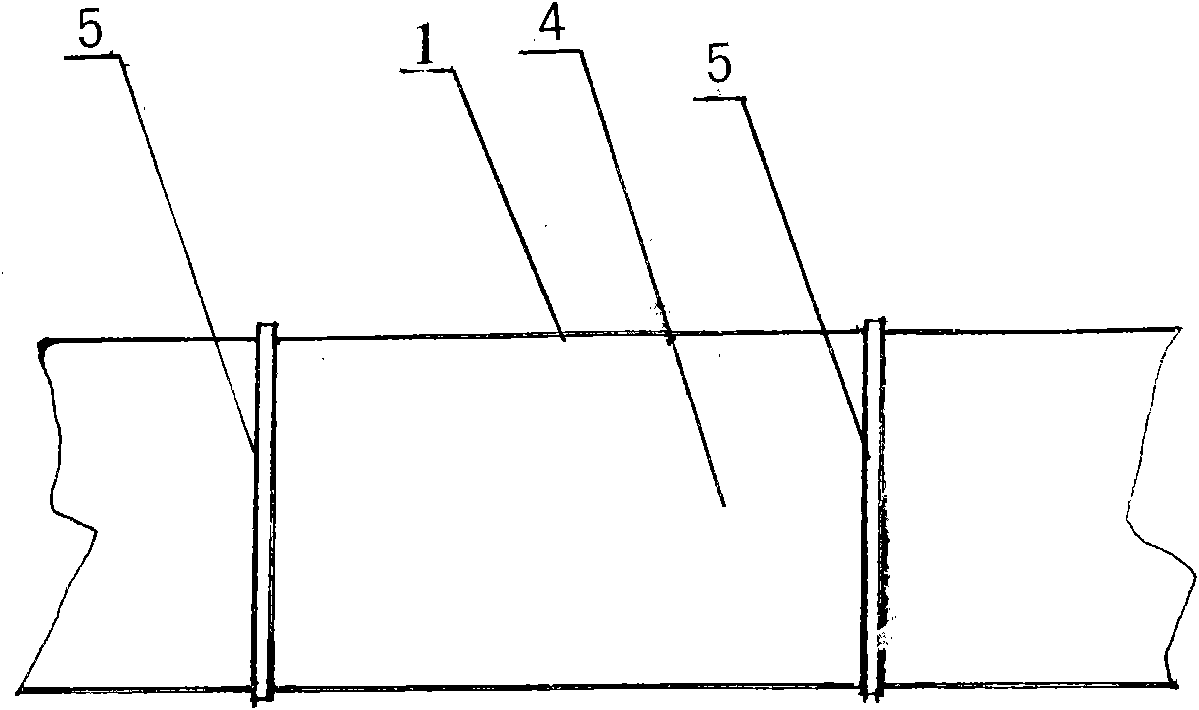
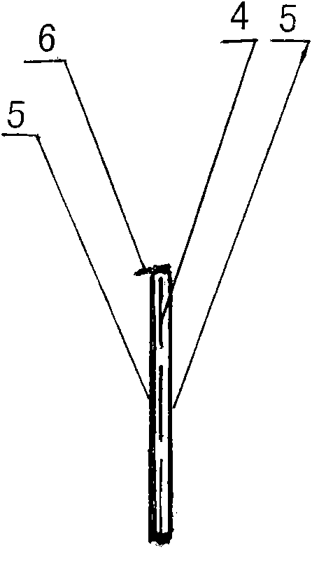
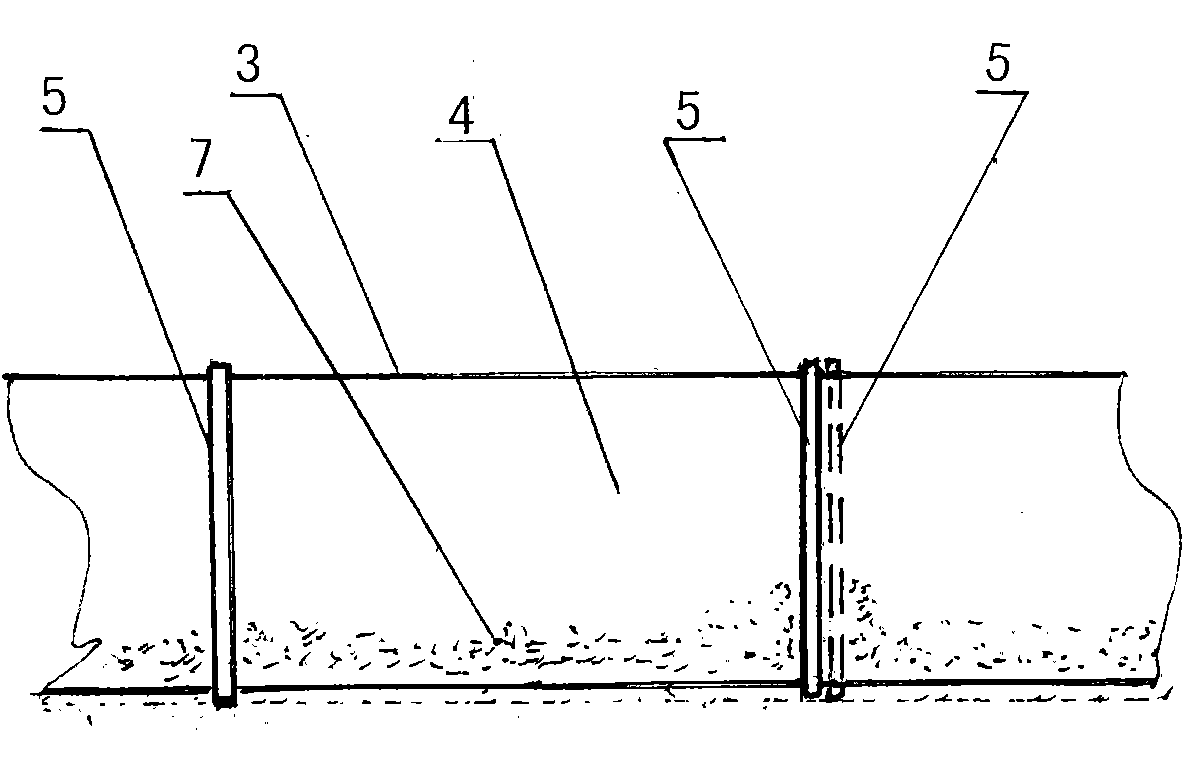
[0015] Show now figure 1 , 2 Further description of the eight-shaped net cage sand barrier of the present invention: the eight-shaped net cage sand barrier is composed of two front and rear net cage pieces, the front net cage piece 1 and the rear net cage piece 2 have the same structure and size, and can be interchanged , the cage sheet is made of a plastic wire mesh with a porosity between 10% and 25% and a width between 25cm and 50cm as the cage surface 4. The porosity and width can be selected within the above range according to needs. Size, interval 50cm is provided with a support rod 5 on the cage surface, and the support rod is tightly stretched on the cage surface, and the top edge and the bottom edge of the support rod and the cage surface vertically intersect and are fixed on the cage surface to form a cage sheet. The support rod 5 longitudinally separates the inner half and the outer half, and the cage surface 4 is tightly embedded in the middle of the inner and out...


PUM

PropertyMeasurementUnit
lengthaaaaaaaaaa
porosityaaaaaaaaaa
porosityaaaaaaaaaa

Abstract

The invention relates to the technical field of engineering, in particular to a splayed cylinder mould sand barrier and a construction structure thereof. The splayed cylinder mould sand barrier is formed by combining a front cylinder mould sheet and a rear cylinder mould sheet, wherein the front cylinder mould sheet and the rear cylinder mould sheet have the same structure and the same dimension and can be interchanged; in the cylinder mould sheets, plastic screen meshes of which the porosity is between 10 and 25 percent and the width is between 25 and 50cm are used as cylinder mould surfaces; a supporting rod is arranged on each cylinder mould surface at intervals of 50cm respectively and supporting rods are fixed with the cylinder mould surfaces to form the cylinder mould sheets; the front cylinder mould sheet and the rear cylinder mould sheet are tightened in the left and right directions; the top edges of the front cylinder mould sheet and the rear cylinder mould sheet are mutually close, and the bottom edges of the front cylinder mould sheet and the rear cylinder mould sheet are separated to form a splayed shape; the top of the supporting rod of the front cylinder mould sheet and the top of the supporting rod of the rear cylinder mould sheet are mutually close and are staggered and intersected; and a clamp hook at the top of the supporting rod faces down to clamp the top edge of the opposite cylinder mould sheet to form the splayed cylinder mould sand barrier. Splayed cylinder mould sand barriers are spliced one by one left and right on a desert in the same construction structure, and the splayed cylinder mould sand barriers extend dozens of meters, hundreds of meters, thousands of meters, dozens of kilometers and hundreds of kilometers along a design line.

Description

technical field [0001] The invention relates to the technical field of engineering, in particular to a figure-eight-shaped net cage sand barrier and its construction structure. Background technique [0002] At present, the mechanical sand barriers used in desertification control projects mainly use firewood, grass, straw, branches, pebbles, clay and plastic nets to set various forms of obstacles on the desert to block and fix sand. In arid desertified areas, because plant seedlings cannot grow in quicksand, ecological restoration often fails. Therefore, the status and role of mechanical sand barriers that can quickly fix quicksand without water are extremely important in sand control. The existing mechanical sand barriers are divided into three categories: one is flat sand barriers, the other is semi-concealed sand barriers, and the other is vertical sand barriers; Laying barriers all over the desert requires a large amount of materials and high cost, so it cannot be used o...

Claims


Application Information

Patent Timeline
Patent Type & Authority Applications(China)
IPC IPC(8): E01F7/02E02D3/00
Inventor 娄志平
Owner 娄志平
Why Eureka
Try Eureka