Cooling device of a power unit

A technology of power unit and cooling device, which is applied in the direction of engine cooling, liquid cooling, engine components, etc., can solve the problems of power unit enlargement, temperature rise, and distance shortening, etc., and achieve miniaturization, improvement of cooling efficiency, and cooling The effect of improving efficiency

Active Publication Date: 2011-04-06
HONDA MOTOR CO LTD
View PDF8 Cites 6 Cited by
  • Summary
  • Abstract
  • Description
  • Claims
  • Application Information

AI Technical Summary

Problems solved by technology

[0004] However, in the conventional structure, a cylindrical oil cooler is arranged around the side wall of the cylinder, so the oil cooler protrudes and is bulky, leading to an increase in the size of the power unit.
In addition, since the oil cooler is arranged at the lower part of the crankcase, the distance between the oil pan and the oil cooler is shortened, and the oil cooler is affected by the oil temperature in the oil pan so that the temperature rises.

Method used


Image

  • Cooling device of a power unit
  • Cooling device of a power unit
  • Cooling device of a power unit

Examples


Embodiment Construction

[0060] Hereinafter, one embodiment of the present invention will be described with reference to the drawings.

[0061]In addition, in the following description, the description about the front-back, left-right, and up-down directions is the same as the direction in a vehicle unless otherwise specified. In addition, in the figure, arrow F indicates the front of the vehicle body, arrow R indicates the right side of the vehicle body, and arrow U indicates the upper side of the vehicle body.

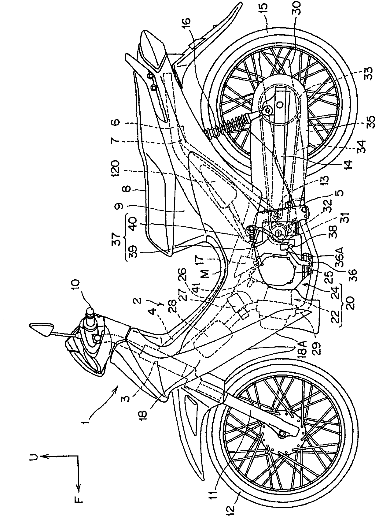
[0062] figure 1 It is a side view showing the motorcycle 1 to which the embodiment of the present invention is applied.

[0063] The body frame 2 of the motorcycle 1 has: a head pipe 3 at the front of the vehicle body; a main frame 4 extending obliquely downward from the head pipe 3 to the rear; extending downward and fixed to the main frame. A pair of left and right pivot brackets 5 at the rear of the main frame 4; a pair of left and right seat rails 6, which extend obliquely upward from ...


PUM


Abstract

The invention provides a cooling device of a power unit, capable of preventing an oil cooler from projecting. The cooling device comprises an oil cooler (105) and the oil cooler comprises: an oil path (108) for the oil supplied to an engine (20) as the power unit; a cooler cooling mechanism (109) for cooling the oil through the oil path (108), wherein the oil cooler (105) extends upwards along the axle of the cylinder (L1) and is formed into the plate shape at the side of the cylinder (22A).

Description

technical field [0001] The invention relates to a cooling device for a power unit. Background technique [0002] Patent Document 1 discloses a structure in which a cylindrical oil cooler (for example, Refer to Patent Document 1). [0003] Patent Document 1: Japanese Patent Laid-Open No. 2003-314277 [0004] However, in the conventional structure, the cylindrical oil cooler is disposed around the cylinder side wall, so the oil cooler protrudes and is bulky, leading to an increase in the size of the power unit. In addition, since the oil cooler is arranged in the lower part of the crankcase, the distance between the oil pan and the oil cooler is shortened, and the temperature of the oil cooler rises due to the influence of the oil temperature in the oil pan. Contents of the invention [0005] The present invention was made in view of the above circumstances, and an object of the present invention is to provide a cooling device for a power unit capable of suppressing protr...

Claims


Application Information

Patent Timeline
Patent Type & Authority Applications(China)
IPC IPC(8): F01P3/02F01P11/08F01P5/02B62J41/00
Inventor 阿部克哉泷口亲司舩山芳浩
Owner HONDA MOTOR CO LTD
Why Eureka
Try Eureka