Auxiliary compressor defrosting system for air source heat pump

An auxiliary compressor, air source heat pump technology, applied in compressors, refrigerators, lighting and heating equipment, etc., can solve the problems of long defrosting time, hidden safety hazards of compressors, and reduced heat supply, and achieve low cost. , Improve indoor comfort and reduce the effect of suction superheat

Inactive Publication Date: 2012-03-07
HARBIN INST OF TECH
View PDF0 Cites 0 Cited by
  • Summary
  • Abstract
  • Description
  • Claims
  • Application Information

AI Technical Summary

Problems solved by technology

[0005] In order to solve the problems that the compressor in the current air source heat pump defrosting system not only provides heat to the room but also provides energy for defrosting, resulting in reduced heat supply to the room, long defrosting time and potential safety hazards in the compressor, the present invention provides An air source heat pump auxiliary compressor defrosting system

Method used


Image

  • Auxiliary compressor defrosting system for air source heat pump
  • Auxiliary compressor defrosting system for air source heat pump

Examples


specific Embodiment approach 1

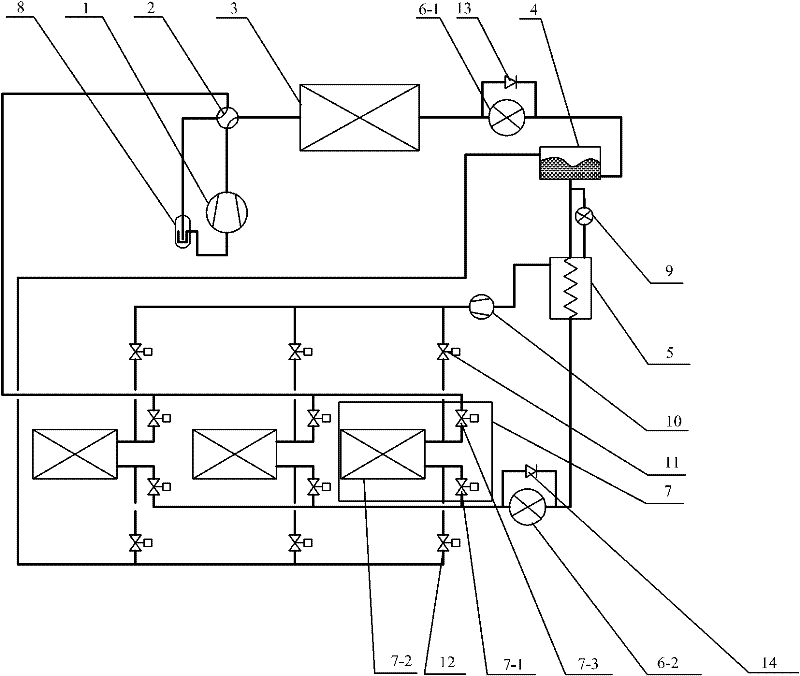
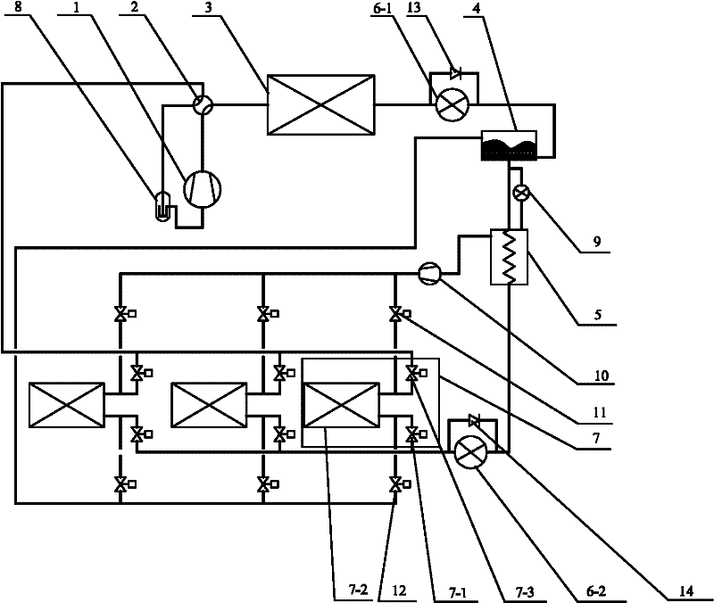
[0009] Specific implementation mode one: combine figure 1 Describe this embodiment, the system of this embodiment includes a main compressor 1, a four-way reversing valve 2, an indoor unit 3, a liquid receiver 4, a first throttle valve 6-1, a second throttle valve 6-2, Multiple outdoor units 7 and gas-liquid separators 8 are arranged in parallel. Each outdoor unit 7 is composed of a first electromagnetic valve 7-1, an outdoor unit 7-2 and a second electromagnetic valve 7-3. The first The solenoid valve 7-1, the outdoor unit 7-2 and the second solenoid valve 7-3 are arranged in series in sequence, the outlet port of the compressor 1 communicates with one of the ports of the four-way reversing valve 2, and the port of the four-way reversing valve 2 One of the remaining three ports communicates with the inlet port of the indoor unit 3, the outlet port of the indoor unit 3 communicates with the inlet port of the first throttle valve 6-1, and the outlet port of the first throttle v...

specific Embodiment approach 2

[0010] Specific implementation mode two: combination figure 1 Describe this embodiment, the system of this embodiment also includes a first one-way valve 13 and a second one-way valve 14, the first throttle valve 6-1 is arranged in parallel with the first one-way valve 13, the second throttle valve 6 -2 is set in parallel with the second one-way valve 14, when heating in winter, open the first one-way valve 13, close the second one-way valve 14, the refrigerant passes through the first one-way valve 13 (not through the first throttling Valve 6-1) flows into the liquid receiver 4, so that the refrigerant is throttled at the second throttle valve 6-2; when running in summer, the first one-way valve 13 is closed, the second one-way valve 14, refrigeration The refrigerant flows through the second one-way valve 14, so that the refrigerant is throttled at the first throttle valve 6-1. The function of the first one-way valve 13 and the second one-way valve 14 is exactly to ensure th...


PUM


Abstract

The invention discloses an auxiliary compressor defrosting system for an air source heat pump and relates to an air source heat pump defrosting system. The invention aims at solving the problems of low indoor heat supply, long defrosting time and potential safety hazard of the compressor as a result of the fact that the compressor in the traditional air source heat pump defrosting system needs tosimultaneously supply heat indoor and supply energy for defrosting. A liquid reservoir is communicated with a subcooler, a pipeline between the liquid reservoir and the subcooler is connected with anexpansion valve in parallel, the subcooler is communicated with the inlet end of an auxiliary compressor, the auxiliary compressor is respectively communicated with a plurality of outdoor machines bya third electromagnetic valve, each outdoor machine is communicated with the liquid reservoir by a fourth electromagnetic valve, the remaining one of two outlet ends of the subcooler is communicated with the inlet end of a second throttling valve, the second throttling valve is connected with a second one-way valve in parallel, the second throttling valve is respectively communicated with a plurality of outdoor units, each outdoor unit is communicated with a four-way reversing valve, and the four-way reversing valve is communicated with a main compressor by a gas-liquid separator. The invention is used for defrosting an air source heat pump.

Description

technical field [0001] The invention relates to an air source heat pump defrosting system. Background technique [0002] When the air source heat pump is running in winter, frost will form on the outdoor unit of the air-cooled heat pump chiller and hot water unit. When the frost layer accumulates to a certain extent, the heating capacity will be significantly attenuated, and defrosting must be carried out. The commonly used defrosting methods mainly include reverse cycle defrosting and hot gas bypass defrosting. [0003] Reverse cycle defrosting is the most common defrosting method. However, this defrosting method has many disadvantages: 1. When defrosting, it needs to absorb heat from the room, and the room temperature will drop by 5-6°C, which will affect the comfort of the room; 2. When switching between heating and defrosting modes, the system pressure fluctuates violently. The mechanical impact generated is relatively large; 3. The indoor heat exchanger is used as an ...

Claims


Application Information

Patent Timeline
Patent Type & Authority Patents(China)
IPC IPC(8): F25B47/02F25B31/00F25B41/04F25B41/06
Inventor 姜益强姚杨董建锴邱国栋
Owner HARBIN INST OF TECH
Why Eureka
Try Eureka