
Anti-interference infrared remote control signal receiving circuit

A technology of remote control signal and infrared remote control, applied in the field of infrared remote control signal receiving circuit, can solve the problems of decreased accuracy of received signal, no obstruction, short communication distance, etc., so as to improve the receiving accuracy, improve the accuracy, and facilitate the acceptance. Effect

Inactive Publication Date: 2011-04-06
广东欧加控股有限公司
View PDF7 Cites 2 Cited by
  • Summary
  • Abstract
  • Description
  • Claims
  • Application Information

AI Technical Summary

Problems solved by technology

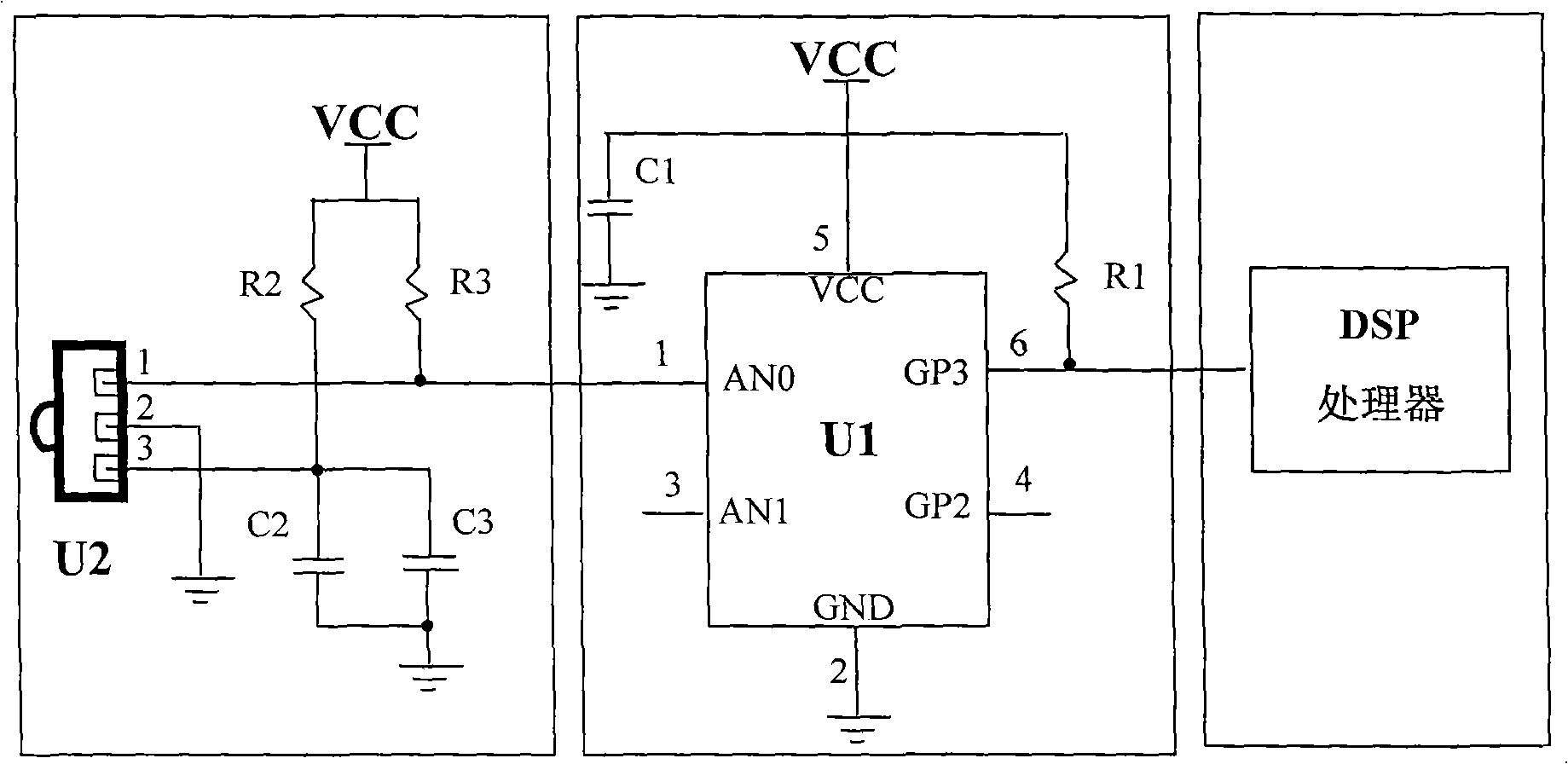
[0003] The existing infrared remote control signal receiving circuit such as figure 1 As shown, the circuit is composed of a remote control signal receiving circuit and a remote control signal processing circuit connected to each other. The communication distance is short; second, there are many infrared emission sources in real life scenes, which interfere with the infrared remote control signal and seriously reduce the accuracy of receiving signals
However, most of the existing infrared remote control devices do not have anti-interference ability, and cannot accurately identify infrared signals mixed with interference clutter.
Although a small part has a certain error correction ability, and has the ability to identify and correct the interference caused by some specific interference clutter on a specific signal, the application occasions of the products are various, and the form of interference clutter It is also varied, and the interference received by the remote control signal is random

Method used


Image

  • Anti-interference infrared remote control signal receiving circuit
  • Anti-interference infrared remote control signal receiving circuit
  • Anti-interference infrared remote control signal receiving circuit

Examples


Embodiment Construction

[0014] The gist of the present invention is to overcome the deficiencies of the prior art and provide an anti-jamming infrared remote control signal receiving circuit, which can receive and process multiple infrared remote control signals, and can effectively remove the interference clutter in the infrared remote control signal, improve the reception Accuracy. The following will describe in detail with reference to the accompanying drawings in conjunction with the embodiments, so as to further explain the technical features and advantages of the present invention.

[0015] The principle block diagram of the present invention is as figure 2 As shown, an anti-interference infrared remote control signal receiving circuit is sequentially composed of a remote control signal receiving circuit, a remote control signal anti-interference circuit and a remote control signal processing circuit connected to each other. The infrared remote control receiving circuit receives and demodulat...


PUM


Abstract

The invention discloses an anti-interference infrared remote control signal receiving circuit, which consists of a remote control signal receiving circuit, a remote control signal anti-interference circuit and a remote control signal processing circuit mutually connected in turn. The infrared remote control receiving circuit receives and demodulates infrared remote control signals through remote control receiving heads; a plurality of the remote control receiving heads are distributed on different parts and in different directions; the remote control signal anti-interference circuit is used for detecting and removing interference noise in the signals and correcting the interfered signal waveform; and the remote control signal processing circuit is responsible for recognizing and processing remote control commands. The anti-interference infrared remote control signal receiving circuit with anti-interference function is designed as a single circuit, can process the infrared remote control signals transmitted by multi-path infrared remote control receiving heads, can effectively remove the interference noise in the infrared remote control signals, and improves the accuracy of a digital signal processor (DSP) for receiving the infrared remote control commands in the remote control signal processing circuit.

Description

technical field [0001] The invention relates to an infrared remote control signal receiving circuit, in particular to an anti-interference infrared remote control signal receiving circuit. Background technique: [0002] Infrared remote control technology is a point-to-point communication technology using infrared rays, and its corresponding software and hardware technologies are relatively mature. Its main technical advantages are: first, there is no need to apply for a specific frequency license; second, it has the characteristics of small size and low power required by mobile communication equipment; third, the transmission rate is suitable for home and office use network; Fourth, the cost is low. Therefore, infrared remote control technology is widely used in various electronic products. [0003] The existing infrared remote control signal receiving circuit such as figure 1 As shown, the circuit is composed of a remote control signal receiving circuit and a remote cont...

Claims


Application Information

Patent Timeline
Patent Type & Authority Applications(China)
IPC IPC(8): G08C23/04
Inventor 林尚波陈昌明苏上丁
Owner 广东欧加控股有限公司
Learn More