Explosion-proof combined cap of high-power battery

A power battery, high-power technology, used in battery pack components, circuits, electrical components, etc., can solve the problems of poor welding firmness, low welding strength, instability, etc., and improve the connection strength and deformation resistance. , Improve the surface anti-oxidation ability, improve the effect of high current passing ability

Inactive Publication Date: 2011-04-06
杨学新
View PDF4 Cites 8 Cited by
  • Summary
  • Abstract
  • Description
  • Claims
  • Application Information

AI Technical Summary

Problems solved by technology

The first is to add a nickel sheet or copper sheet between the explosion-proof disc and the nickel-plated steel cap. The disadvantages are high cost, large resistance and instability (1~3mΩ)
The second connection method is to use laser spot welding connection. Its disadvantages include: the welding strength of laser spot welding connection is not high; the resistance of the welding place is generally 0.5mΩ, and the deformation after sealing will cause the resistance value to change; After a large current passes through the explosion-proof disk, the aluminum surface will be oxidized, which will increase the contact resistance and affect the flow capacity; the surface of the nickel-plated steel cap will damage the nickel-plated layer due to laser welding spots, resulting in a decrease in anti-rust ability, thereby affecting the reliability of later use. sex
The third connection method is to use ultrasonic or resistance welding connection. Its disadvantages include: because the surface is damaged during ultrasonic welding, the burrs on the surface will cause a short circuit when the battery is sealed, and the control is difficult; the welding firmness is not good. And the resistance value is too large

Method used


Image

  • Explosion-proof combined cap of high-power battery
  • Explosion-proof combined cap of high-power battery
  • Explosion-proof combined cap of high-power battery

Examples


Embodiment Construction

[0018] The following examples are used to illustrate the present invention, but are not intended to limit the scope of the present invention.

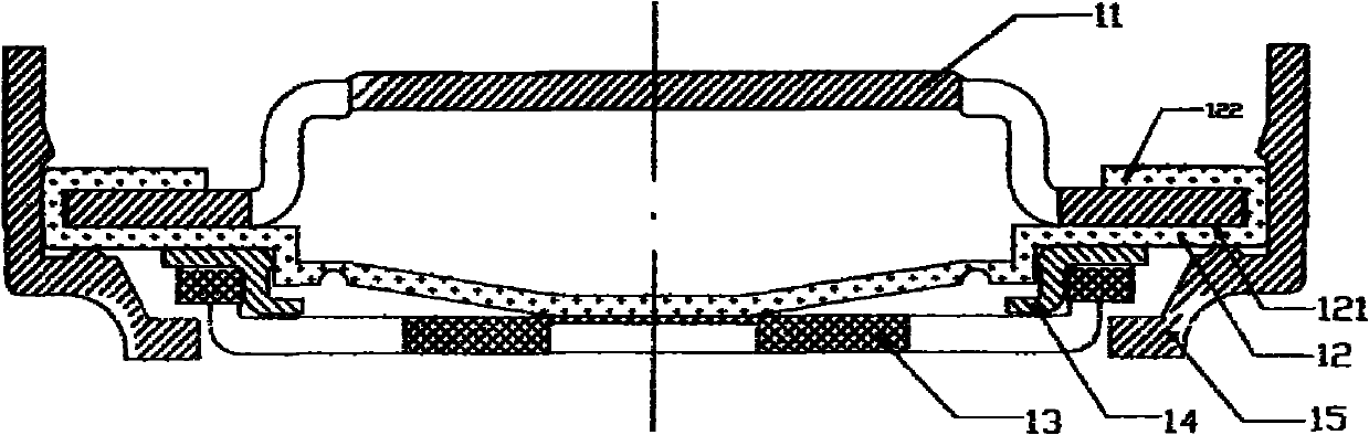
[0019] figure 1 It is a schematic cross-sectional view of an embodiment of an explosion-proof combination cap for a high-power power battery of the present invention. As shown in the figure, the explosion-proof combination cap 10 of this embodiment includes a steel cap 11, an explosion-proof plate 12, a connecting piece 13, an isolation ring 14 and the above four elements. Or the sealing ring 15 covered by the outer circumference. In particular, in the combined cap embodiment of the present invention, a nickel-plated layer 121 is added on the surface of the explosion-proof disk 12 , and a solder connection is adopted between the steel cap 11 and the explosion-proof disk 12 .

[0020] continue as figure 1 As shown, in this embodiment, the explosion-proof disk 12 is an aluminum sheet with a nickel-plated layer 121 on its inner surface,...


PUM


Abstract

The invention relates to an explosion-proof combined cap of a high-power battery, which is composed of a steel cap (11), an explosion-proof plate (12), a connecting plate (13), a spacing ring (14) and sealing rings (15), wherein the outer circumferences of the steel cap (11), the explosion-proof plate (12), the connecting plate (13) and the spacing ring (14) are covered with the sealing rings (15); and the surface of the explosion-proof plate (12) is provided with a nickel plating layer (121), and the steel cap (11) and the explosion-proof plate (12) are welded by way of tin soldering. The explosion-proof combined cap of the invention can guarantee the low resistivity / consumption and high-power through-current capabilities of the battery when the battery runs normally; and when the battery runs exceptionally, the inner part of the battery can be disconnected reliably, therefore, the security protection function of the explosion-proof combined cap is played more effectively.

Description

technical field [0001] The invention relates to a high-power power battery, in particular to an explosion-proof combination cap of an ultra-low resistance high-power cylindrical power battery. Background technique [0002] In the prior art, there are usually three connection modes between the explosion-proof disk (aluminum) and the nickel-plated steel cap included in the combined cap for cylindrical batteries. The first is to add a nickel sheet or copper sheet between the explosion-proof disc and the nickel-plated steel cap. The disadvantages are high cost, large resistance and instability (1-3mΩ). The second connection method is to use laser spot welding connection. Its disadvantages include: the welding strength of laser spot welding connection is not high; the resistance of the welding place is generally 0.5mΩ, and the deformation after sealing will cause the resistance value to change; After a large current passes through the explosion-proof disk, the aluminum surface w...

Claims


Application Information

Patent Timeline
Patent Type & Authority Applications(China)
IPC IPC(8): H01M2/04H01M2/08H01M2/12
CPCY02E60/12Y02E60/10
Inventor 杨学新
Owner 杨学新
Why Eureka
Try Eureka