Megawatt-grade permanent magnet generator

A permanent magnet generator, megawatt-level technology, applied in the direction of electric components, electrical components, electromechanical devices, etc., can solve the problems of uneven cooling, local overheating, etc., and achieve the effects of uniform axial direction, quick installation and reasonable distribution

Active Publication Date: 2011-04-06
DONGFANG ELECTRIC MACHINERY
View PDF8 Cites 6 Cited by
  • Summary
  • Abstract
  • Description
  • Claims
  • Application Information

AI Technical Summary

Problems solved by technology

The above ventilation methods can cool the motor, but they all have uneven cooling and even local overheating. In order to ensure the normal operation

Method used


Image

  • Megawatt-grade permanent magnet generator
  • Megawatt-grade permanent magnet generator
  • Megawatt-grade permanent magnet generator

Examples


Example Embodiment

[0032] Example 1

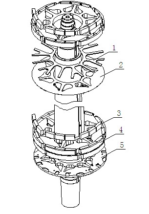
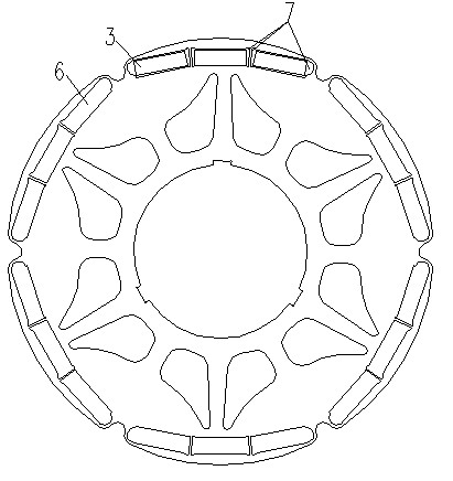
[0033] The invention discloses a megawatt permanent magnet generator, including a rotor magnet fixed structure and a motor ventilation structure, etc., with reference to Figure 1~2 . The fixed structure of the magnetic steel includes a rotor core disk 4, a plurality of core disks 4 are fixed on the rotating shaft by a square key, and two adjacent core disks 4 are separated by a stainless steel ventilation slot plate 1, and two ends of the rotor core are provided The stainless steel iron core pressing plate 5 has a plurality of magnetic steel grooves 6 on the iron core punching piece close to the outer circle of the iron core plate 4, and the shape of the magnetic steel groove 6 matches the shape of the magnet 3 to be assembled. The circumference is evenly distributed. The magnetic steel grooves 6 are in six groups, each group includes three rectangular magnetic steel grooves 6, and a gap 7 is left at the edge of the matching part between the magnetic steel gr...

Example Embodiment

[0035] Example 2

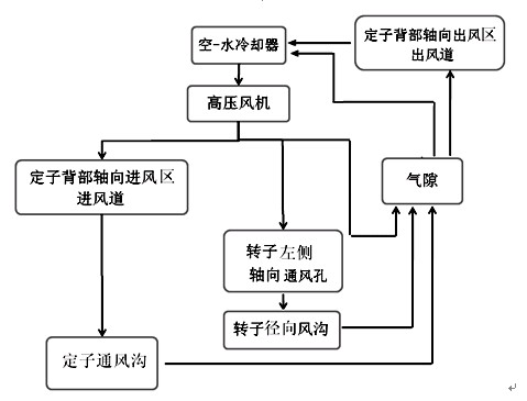
[0036] As a best embodiment of the present invention, refer to Figure 3~6 The motor ventilation structure includes a cooler set above the motor and a forced ventilation centrifugal fan 1 provided with the cooler. A plurality of air inlet areas 2 and air outlet areas 3 are alternately arranged on the back 4 of the stator core of the motor. The zone 2 and the air outlet zone 3 are evenly distributed along the radial circumference of the motor, wherein the air inlet zone 2 is open at the air inlet end 6 of the centrifugal fan 1 and closed at the air outlet end 7 of the centrifugal fan 1; 3 The air outlet 7 of the centrifugal fan 1 is open, and the air inlet 6 of the centrifugal fan 1 is closed. A plurality of stator ventilation grooves 10 distributed along the radial direction of the motor are provided in the stator core 8, and also in the rotor core 9 There are a plurality of rotor ventilation grooves 11 distributed along the radial direction of the motor. The ...


PUM

PropertyMeasurementUnit
Heightaaaaaaaaaa
Heightaaaaaaaaaa

Abstract

The invention discloses a megawatt-grade permanent magnet generator relating to the technical field of permanent magnet generators. The megawatt permanent magnet generator comprises a rotor magnet steel fixing structure, a rotor magnet steel mounting tool, a motor ventilation structure and the like, wherein the rotor magnet steel fixing structure comprises a plurality of rotor core plates which are fixed on a rotating shaft trough square keys, every two adjacent core plates are separated by a stainless steel ventilating duct plate to form a radial rotor ventilating duct, stainless steel rotorcore pressing plates are respectively arranged at both ends of a rotating shaft core, and a plurality of magnetic steel slots are arranged on a core punching sheet close to the excircle of either core plate, matched with magnetic steel to be assembled in shape, and uniformly distributed on the circumference. The rotor has very simple structure and can be easily and conveniently assembled, the magnetic steel can be rapidly mounted, additional magnetic steel fasteners or other complicated fixing modes are not needed, the magnetic steel can be prevented from loosening or falling off, and the long-term, normal, reliable and safe operation of the motor is ensured.

Description

[0001] technical field [0002] The invention relates to the technical field of permanent magnet generators, in particular to a megawatt-level permanent magnet generator. Background technique [0003] Megawatt-level permanent magnet generators usually include generator stators, rotors, outlet boxes and other components. In addition, it also includes rotor magnetic steel fixing structure, motor ventilation structure and so on. The existing permanent magnet generator has the following disadvantages: [0004] 1. For the fixed structure of the rotor magnetic steel, the existing permanent magnet motor generally installs the magnetic steel on the rotor, and its structural types include: magnetic steel embedded - the rotor punch is punched with a magnetic steel groove, and the magnetic steel is installed in the groove. This kind of structural form fully guarantees the symmetry of the magnetic steel slot when the punching sheet is manufactured, thereby ensuring the symmetry of...

Claims


Application Information

Patent Timeline
IPC IPC(8): H02K1/27H02K1/32H02K9/04H02K1/20
Inventor 赵长青唐小国
Owner DONGFANG ELECTRIC MACHINERY
Why Eureka
Try Eureka