Electronic image stabilization method based on characteristic straight line of ship-borne camera system
A feature line and camera system technology, applied in the field of image processing, can solve the problems of inability to ensure high matching accuracy, difficulty in ensuring real-time image stabilization, and low parameter solution accuracy, achieving reduced feature selection, good real-time performance, and computational low-complexity effects
- Summary
- Abstract
- Description
- Claims
- Application Information
AI Technical Summary
Problems solved by technology
Method used
Image

Examples
Embodiment Construction
[0026] The present invention will be further described below in conjunction with the accompanying drawings.
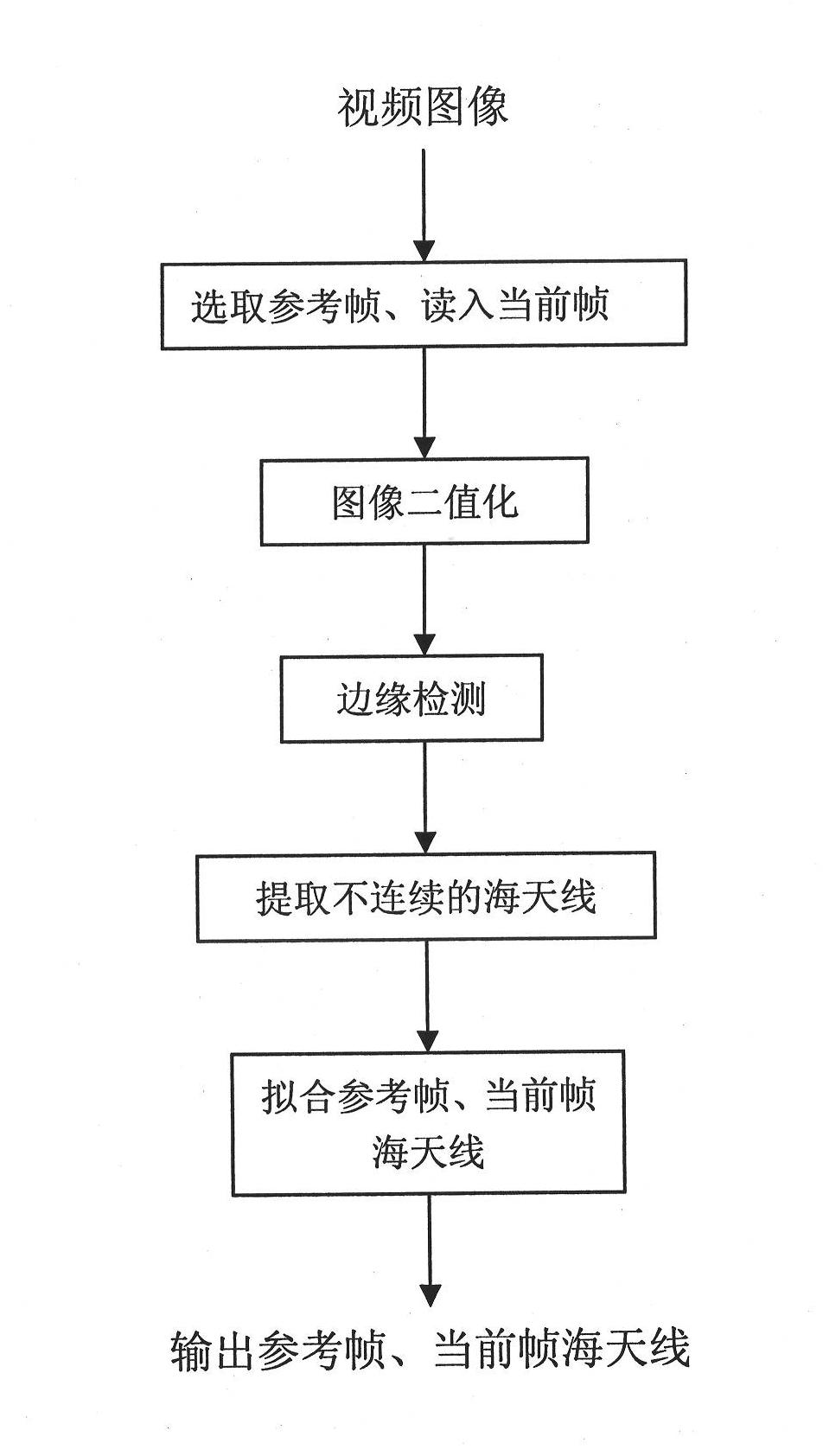
[0027] Step 1. Select a reference frame and read in the current frame.
[0028] In order to eliminate the image shift and rotation caused by the shaking of the camera system and realize the stabilization of each frame of image on the camera system, it is necessary to select a stable frame of image from the video images being captured by the camera system and use it as image stabilization processing Frame of reference for translation and rotation. The video image sequence being shot is read into the image stabilization system one by one in sequence as the current frame to be stabilized.
[0029] Step 2, image binarization.
[0030] In the video images of the navigation process, the sea and the sky occupy most of the area, and there are obvious differences between the grayscale of the sea and the grayscale of the sky. Using the method of image binarization to enhance t...
PUM
 Abstract
Description
Claims
Application Information
 - R&D
- Intellectual Property
- Life Sciences
- Materials
- Tech Scout
- Unparalleled Data Quality
- Higher Quality Content
- 60% Fewer Hallucinations
Browse by: Latest US Patents, China's latest patents, Technical Efficacy Thesaurus, Application Domain, Technology Topic, Popular Technical Reports.
© 2025 PatSnap. All rights reserved.Legal|Privacy policy|Modern Slavery Act Transparency Statement|Sitemap|About US| Contact US: help@patsnap.com