Fuel vapor storage and recovery apparatus

A technology of fuel vapor and recycling equipment, which is applied in the direction of mechanical equipment, fuel injection devices, and adding non-fuel substances to fuel, etc., can solve the problem of exhausting the fuel vapor capacity of ordinary carbon tanks, and achieve the effect of improving the desorption and removal rate

Active Publication Date: 2011-04-06
KAUTEX TEXTRON
View PDF8 Cites 6 Cited by
  • Summary
  • Abstract
  • Description
  • Claims
  • Application Information

AI Technical Summary

Problems solved by technology

As a result, the fuel vapor capacity of ordi

Method used


Image

  • Fuel vapor storage and recovery apparatus
  • Fuel vapor storage and recovery apparatus
  • Fuel vapor storage and recovery apparatus

Examples


Embodiment Construction

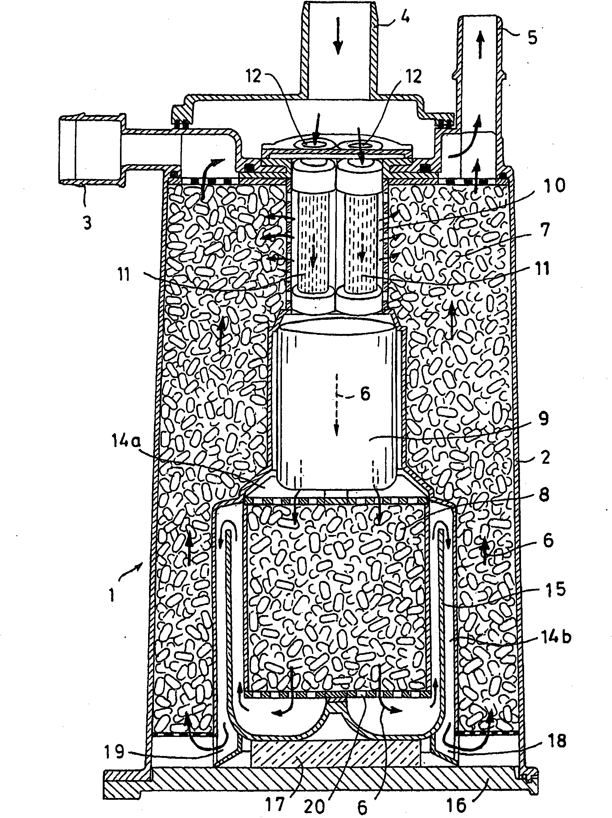
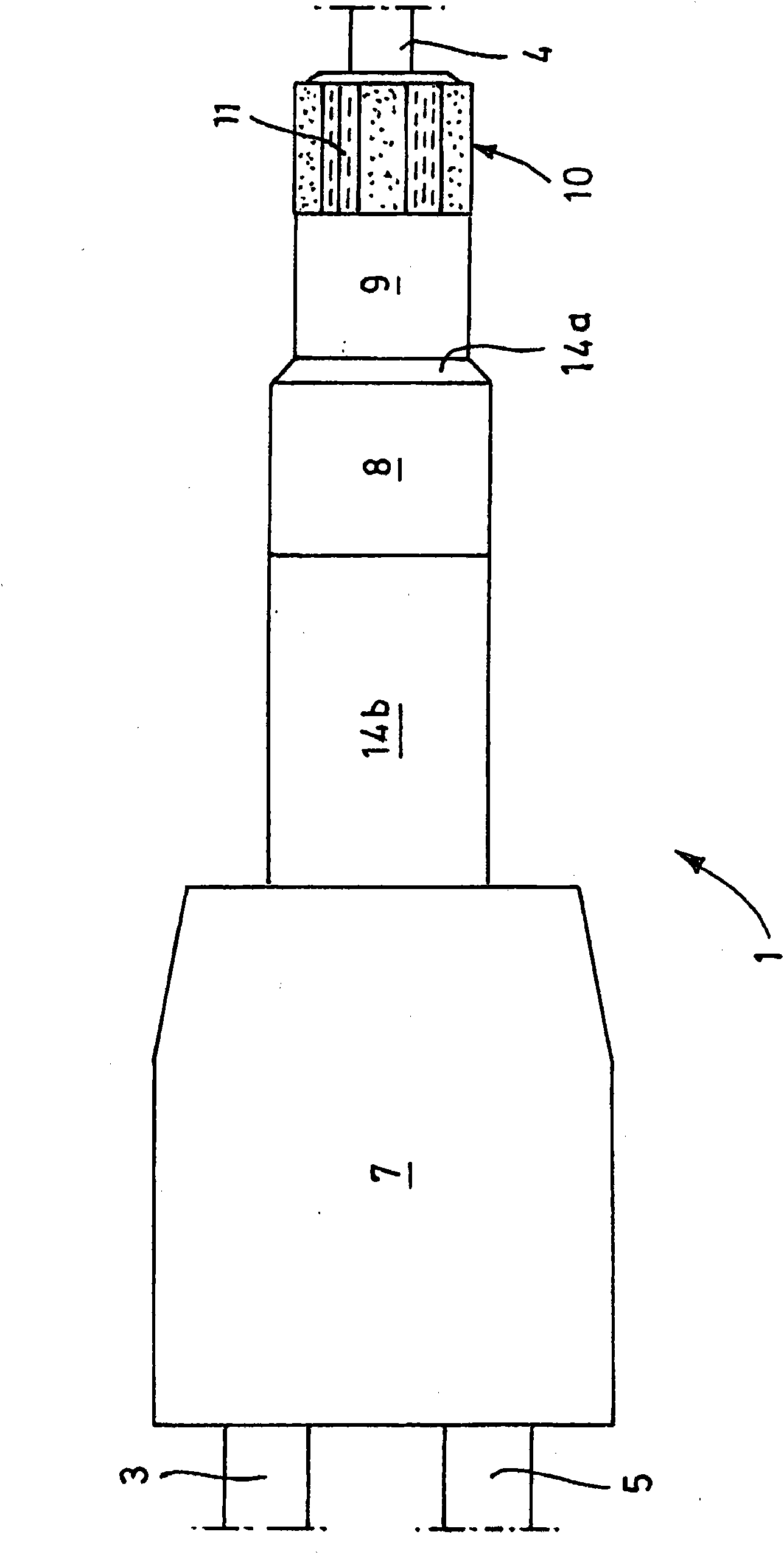
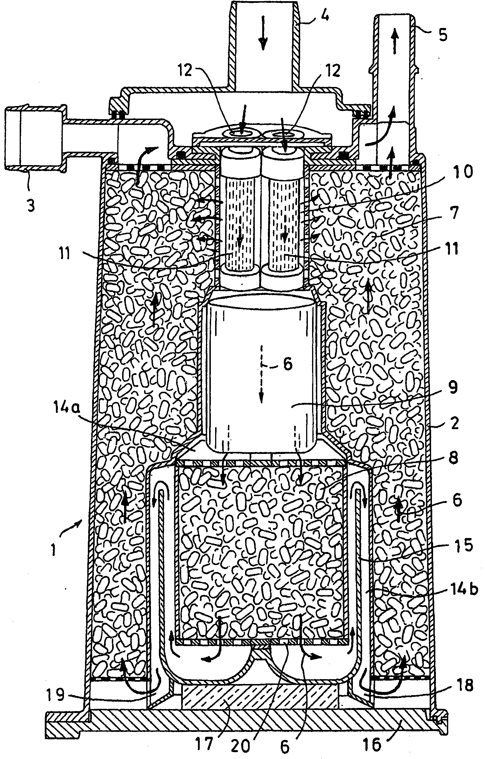
[0034] figure 1 A fuel vapor storage and recovery facility is shown in . The drawings are schematic only and components are not drawn to scale.

[0035] The fuel vapor storage and recovery device 1 includes a steam inlet 3, a vent 4 and a desorption port 5, the vapor inlet 3 is connected to a fuel tank (not shown), the vent 4 is communicated with the atmosphere, and the desorption port 5 is connected to the motor The vehicle's internal combustion engine (also not shown) is connected. The canister 2 contains an adsorbent in the form of granular activated carbon.

[0036] The canister 2 is connected to the fuel tank of the motor vehicle through the vapor inlet 3 and to the atmosphere through the vent 4 during periods when the motor vehicle's engine is stopped.

[0037] As explained at the outset of this application, during a standstill of the vehicle, the fuel in the fuel tank evaporates into the air space above the maximum fill level of the fuel tank. The steam-laden air flow...


PUM


Abstract

A fuel vapor storage and recovery apparatus (1) includes a fuel vapor storage canister, said fuel vapor storage canister comprising at least first and second vapor storage compartments (7, 8) filled with an absorbent material, for instance filled with activated carbon, at least a vapor inlet port (3), an atmospheric vent port (4) and a purge port (5). Said fuel vapor storage canister defines an air flow path between said vapor inlet port (3) and said atmospheric vent port (4) during shut- off of the internal combustion engine of the vehicle. During purging cycles there is defined an air flow path between said atmospheric vent port (4) and said purge port (5) wherein said first and second vapor storage compartments (7, 8) are arranged in concentric relationship and wherein said first and second vapor storage compartments (7, 8) in flow direction are separated from each other by an air gap diffusion barrier.

Description

technical field [0001] The present invention relates to a fuel vapor storage and recovery device for reducing evaporative emissions from motor vehicles. In recent years, fuel vapor storage and recovery apparatus including fuel vapor storage tanks have been known in the art. The gasoline fuel used in many internal combustion engines is very volatile. Evaporative emissions of fuel vapors occur in vehicles with internal combustion engines mainly due to the ventilation of the vehicle's fuel tank. When the vehicle is parked, changes in temperature or pressure allow the air to be laden with hydrocarbons that escape from the fuel tank. Some of the fuel must evaporate into the air within the fuel tank, thereby forming a vapor. If the air exhausted from the fuel tank is allowed to flow untreated into the atmosphere, it must carry fuel vapors with it. There are government regulations on how much fuel vapor can be emitted from a vehicle's fuel system. Background technique [0002]...

Claims


Application Information

Patent Timeline
IPC IPC(8): F02M25/08
CPCF02M25/0854F02M2025/0881
Inventor P·卡顿T·T·黄T·朗U·卡尔施
Owner KAUTEX TEXTRON
Why Eureka
Try Eureka