Aircraft engine mounting vehicle

An aero-engine and installation vehicle technology, applied in aircraft assembly, aircraft parts, ground installations, etc., can solve the problems of high engine loading and unloading costs, low degree of automation, low efficiency, etc., to reduce loading and unloading costs, improve efficiency, and positioning accuracy. high effect

Inactive Publication Date: 2011-04-13
成都立航科技股份有限公司
View PDF5 Cites 36 Cited by
  • Summary
  • Abstract
  • Description
  • Claims
  • Application Information

AI Technical Summary

Problems solved by technology

The disadvantages of this loading and unloading method are mainly manifested in: (1) a special work shed is required, and the cost of engine loading and unloading is very high; (2) because the aircraft needs to be moved to the work shed to carry out loading and unloading operations, the maneuverability is very poor; (3) automation low level, low efficiency

Method used


Image

  • Aircraft engine mounting vehicle
  • Aircraft engine mounting vehicle
  • Aircraft engine mounting vehicle

Examples


Embodiment Construction

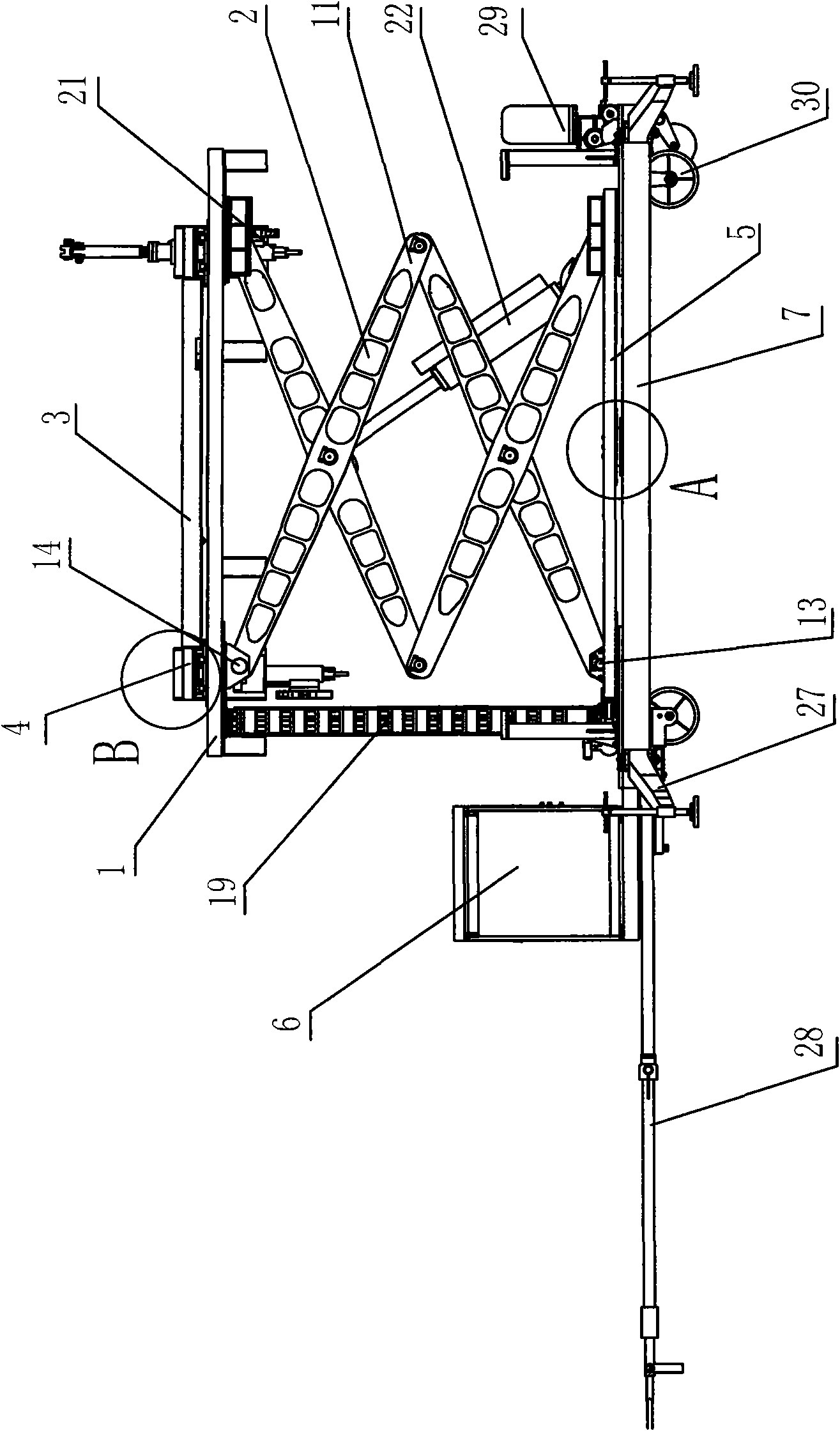
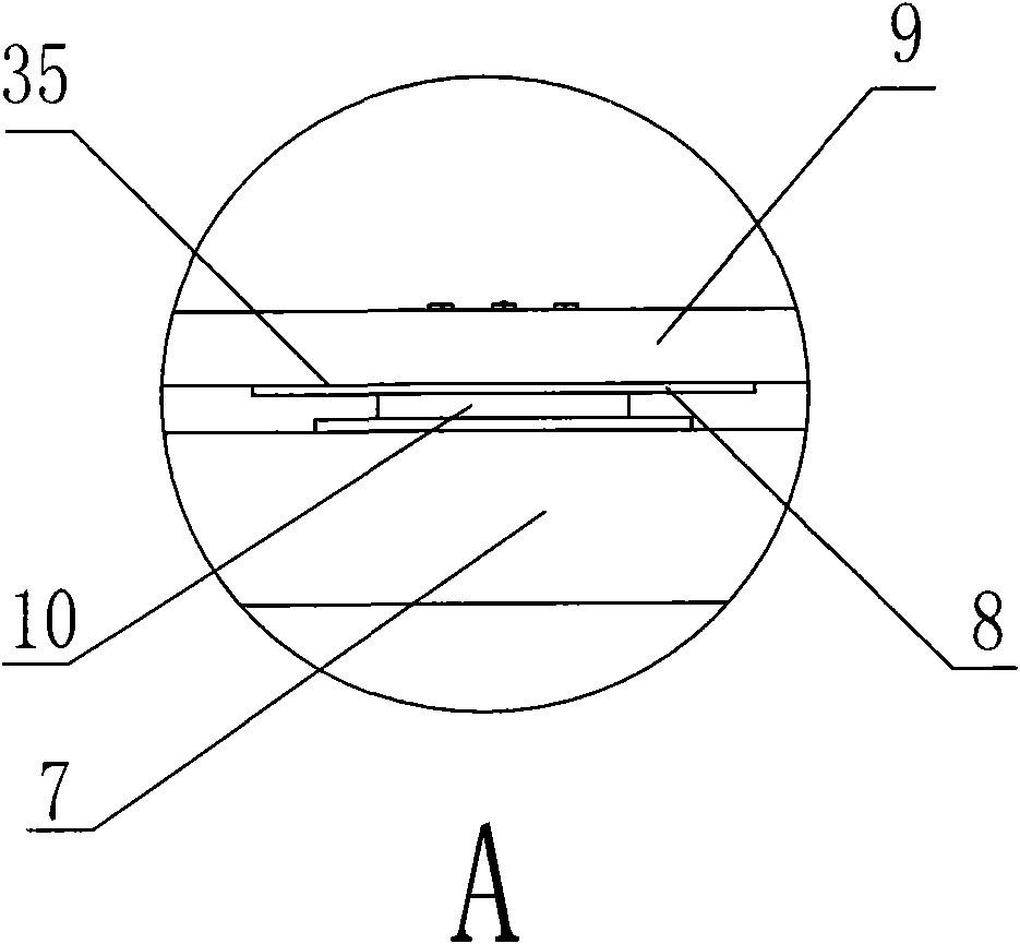
[0025] Below in conjunction with accompanying drawing, the present invention will be further described: as figure 1 , Figure 4 , an aero-engine installation vehicle, comprising a lifting bracket 1, a scissor lift mechanism 2, a front and rear moving frame 3, a left and right moving frame 4, a turntable mechanism 5, an electro-hydraulic servo control system 6 and a car body 7, wherein:

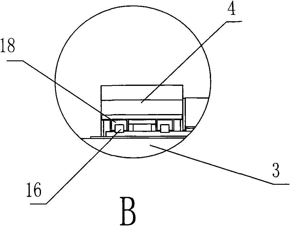
[0026] like image 3 , Figure 5 , the lifting bracket 1 is provided with eight longitudinal linear guide rails 15, the front and rear moving frame 3 is provided with eight transverse linear guide rails 16 and longitudinal sliders 17, the left and right moving frame 4 is provided with horizontal sliders 18, and the longitudinal sliders 17 is located in the longitudinal linear guide rail 15, and the transverse slider 18 is located in the transverse linear guide rail 16. The longitudinal linear guide rail 15 and the transverse linear guide rail 16 are respectively fixed on the front and rear m...


PUM


Abstract

The invention discloses an aircraft engine mounting vehicle. The aircraft engine mounting vehicle comprises a lifting bracket (1), a shear type lifting mechanism (2), a back-and-forth moving frame (3), a left-right moving frame (4), a rotating disk mechanism (5), an electrohydraulic servo control system (6) and a vehicle body (7), wherein the lifting bracket (1) is provided with a longitudinal linear guide rail (15); the back-and-forth moving frame (3) is provided with a transverse linear guide rail (16) and a longitudinal slide block (17); the left-right moving frame (4) is provided with a transverse slide block (18); and the electrohydraulic servo control system (6) comprises a control unit (20) and an executing unit (21). In the aircraft engine mounting vehicle, a closed-loop servo control system consisting of the linear guide rail, a high-accuracy sensor, a high-response spaceflight servo valve, a precise servo oil cylinder and a programmable logic controller (PLC) is adopted, so 0.1mm absolute accuracy fine adjustment can be realized; and the aircraft engine mounting vehicle has the advantages of improving the aircraft engine assembling and disassembling efficiency and reducing the assembling and disassembling cost, along with high assembling, disassembling and positioning accuracy of an engine, and high automation degree and maneuverability.

Description

technical field [0001] The invention relates to a special purpose vehicle, in particular to an aeroengine installation vehicle. Background technique [0002] The engine is the "heart" of a machine and needs frequent inspection and maintenance. Especially for aero-engines, common aero-engines include turbine engines and turbofan engines. The structure of the engine is relatively complicated, and precise positioning is required during installation, debugging, and disassembly. Due to the large mass of the engine and the limited space for the engine to move, it is relatively difficult to lift, laterally translate, longitudinally translate, and adjust the attitude of the engine. [0003] Most of the existing aero-engine installation and disassembly is done in a dedicated work shed. First, the aircraft that needs to be loaded and unloaded must be driven into the work shed, and then the aero-engine installation is completed manually or using some simple installation and support de...

Claims


Application Information

Patent Timeline
Patent Type & Authority Applications(China)
IPC IPC(8): B23P19/04B64F5/00B64F5/10B64F5/50
Inventor 郑愈红周中滔邓敏
Owner 成都立航科技股份有限公司
Why Eureka
Try Eureka