Reactive foam injection system

A reactive and foam technology, applied in the field of construction material supply system, can solve the problems of clogging the front orifice of the gas drainage pipe, uncontrollable flow, waste of raw materials, etc., to improve the uniformity and stability of sealing holes, and save drainage Energy consumption and the effect of reducing construction costs

Active Publication Date: 2012-12-05
CHINA COAL TECH & ENG GRP CHONGQING RES INST CO LTD
View PDF4 Cites 0 Cited by
  • Summary
  • Abstract
  • Description
  • Claims
  • Application Information

AI Technical Summary

Problems solved by technology

This sealing method has the following four important disadvantages: (1) For component B with high viscosity, the dispersing and mixing effect of manual stirring is too poor, which will not only cause waste of raw materials, but also directly affect the subsequent foaming and mixing. Curing effect; (2) Since the interval from the mixing of AB components to foaming is only tens of seconds (usually less than 30 seconds), the reaction type has usually been developed during the process of the gas drainage pipe advancing in the drainage hole. At this time, the friction between the cotton cloth and the coal wall will cause a large number of cells to rupture and merge in the initial foaming stage, which will greatly reduce the sealing effect of the reactive foam; (3) Since the viscosity of the AB component starts to foam rapidly Therefore, the sealing depth of manual sealing is often low (varies with the proficiency of workers, usually less than 3 meters), which is not conducive to avoiding coal seam fissures; (4) The manual sealing process is a reactive type of free hair Bubbles, the strength of the cells is poor, and it is easy to shrink over time, thus losing the sealing ability
This kind of equipment is used for sealing holes. Although it solves the problem of manual reactive foam sealing to a certain extent, it still has the following problems: (1) The "Y"-shaped manifold can only realize the " V"-shaped confluence mixing, and the confluence speed is low, so it is difficult to ensure the uniformity of mixing; (2) The liquid delivery speed of the hand-operated booster device is slow and the delivery speed is limited by the physical strength and proficiency of the operator. When the foaming speed is constant, it is difficult to ensure the uniformity of the quality in sealing or other application processes; (3) The flow rate cannot be controlled, so it is easy to cause insufficient foam filling and poor sealing quality or excessive filling to block gas drainage (4) For the "Y"-shaped manifold, a large amount of cleaning fluid must be used to clean the manifold after each hole is sealed, which is costly and time-consuming; (5) Due to the slow flow rate, this method The application is limited. For example, the sealing depth usually cannot reach more than 8 meters, generally less than 5 meters, and the width of the coal seam fracture zone cannot be avoided.
[0006] The important thing is that the application methods of the above reactive foam materials are all subjective participation of human beings, and the amount of materials used can only be controlled according to experience, resulting in quality problems and unnecessary waste of materials after application

Method used


Image

  • Reactive foam injection system
  • Reactive foam injection system
  • Reactive foam injection system

Examples


Embodiment Construction

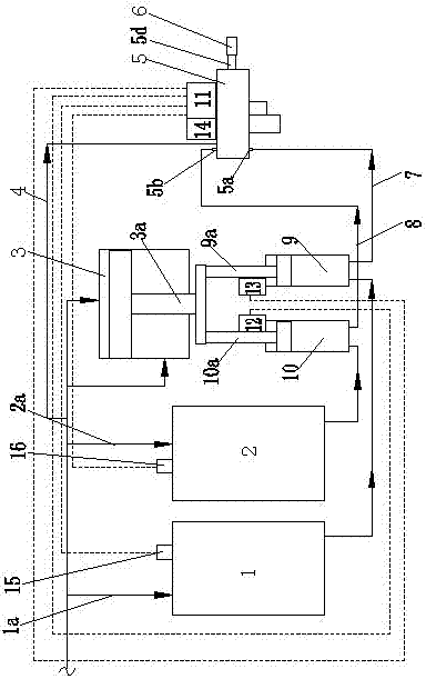
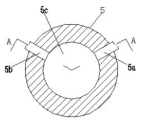
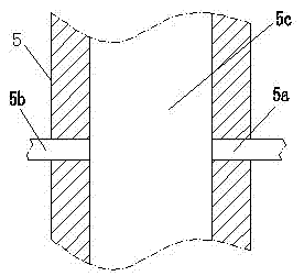
[0032] figure 1 It is a schematic diagram of the structure of the present invention, figure 2 It is a schematic diagram of the flow path of the injection device of the present invention; image 3 for figure 2 A sectional view along the direction of A-A, as shown in the figure: the reactive foam injection system of this embodiment includes a sealing feeding device and a sealing injection device 5;

[0033] The feeding device includes a reactive A foam component feeding device and a reactive foam B component feeding device; the reactive foam A component feeding device includes a component A storage tank 1 and a component A booster Pressure pump 9, the suction port of the A component booster pump 9 is connected to the A component storage tank 1, and the reactive foam B component supply device includes the B component storage tank 2 and the B component booster pump 10 The suction port of the component B booster pump 10 is connected to the reactive type B component storage tan...


PUM


Abstract

The invention discloses a reactive foam injection system, reactive foam components A and B are conveyed into an injection device through a booster pump, and two discharge ports are opposite in a certain angle, thereby leading the reactive components A and B after pressure boost to carry out high-pressure collision and mixing in the injection device; forming turbulent flow, leading the reactive foam components A and B to be rapidly uniformly mixed; ensuring the foaming quality and further ensuring the expansion quality and the curing quality. By adopting the reactive foam injection system, theartificial subjective participation can be eliminated as far as possible, the flow rate of hole sealing material can be automatically controlled, the phenomenon of excessive or insufficient material can be avoided, the construction efficiency can be improved and the construction cost can be reduced; if the reactive foam injection system is used for hole sealing, the phenomenon of the waste of thematerial caused by manual hole sealing can be avoided by utilizing the booster pump and an injection gun structure, the hole sealing can be controlled to realize sufficient depth, air is difficult topermeate into a negative pressure region from micro-fractures of a coal bed, the hole sealing quality is ensured, and the gas extraction efficiency and the extraction concentration can be improved.

Description

technical field [0001] The invention relates to a construction material supply system, in particular to a material supply system which utilizes the characteristics of reaction, foaming, expansion and solidification after two substances are mixed to carry out sealing construction. Background technique [0002] Reactive foam refers to a type of foam material that reacts after the two material components are mixed, foams and expands, and later cures to a predetermined index. It is usually used in sealing, reinforcement and other fields; such as sealing in the process of coal mine gas extraction Hole operation, reactive foam has played a greater role. [0003] In the coal mine gas drainage sealing operation, reactive foam is generally used, and the hole is sealed by using the principle that the reactive A component and the reactive B component are mixed and foamed and solidified, and the mixed foam and solidification have a certain time difference. Because the reactive foam has...

Claims


Application Information

Patent Timeline
Patent Type & Authority Patents(China)
IPC IPC(8): B29C44/42
Inventor 许向彬刘罡胡澜梁全才唐良忠王海燕刘小林叶淑英
Owner CHINA COAL TECH & ENG GRP CHONGQING RES INST CO LTD
Why Eureka
Try Eureka