Electronic mechanical braking device

An electro-mechanical brake and brake disc technology, which is applied in the direction of brake transmission, brake, transportation and packaging, etc., can solve the problems of complex brake device structure, complex brake structure, and difficult loading and application, and achieve effective It is beneficial to the protection of the ecological environment, accurate braking, and the effect of shortening the adjustment time

Inactive Publication Date: 2011-04-13
CHERY AUTOMOBILE CO LTD
View PDF7 Cites 26 Cited by
  • Summary
  • Abstract
  • Description
  • Claims
  • Application Information

AI Technical Summary

Problems solved by technology

[0004] However, in the existing electromechanical braking system, the structure of the braking device is complex, it takes up a large space, and the manufacturing cost is high, so it is difficult to realize the applic...

Method used


Image

  • Electronic mechanical braking device
  • Electronic mechanical braking device
  • Electronic mechanical braking device

Examples


Embodiment Construction

[0025] In order to enable those skilled in the art to better understand the technical solutions of the present invention, the present invention will be further described in detail below in conjunction with the accompanying drawings and specific embodiments.

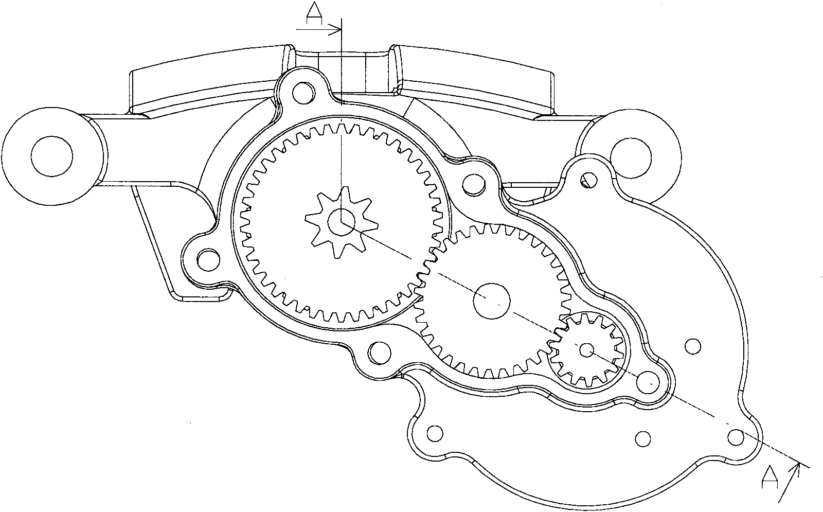
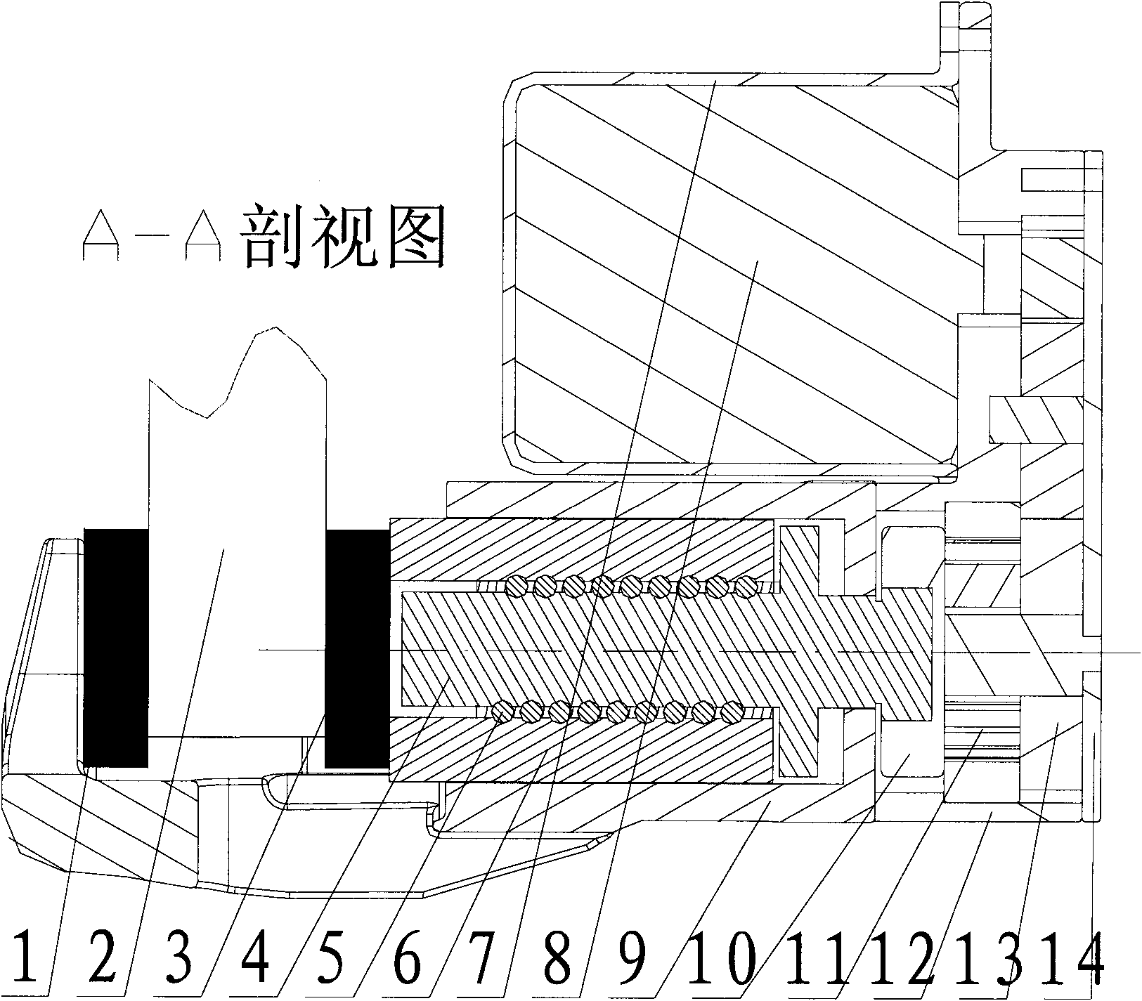
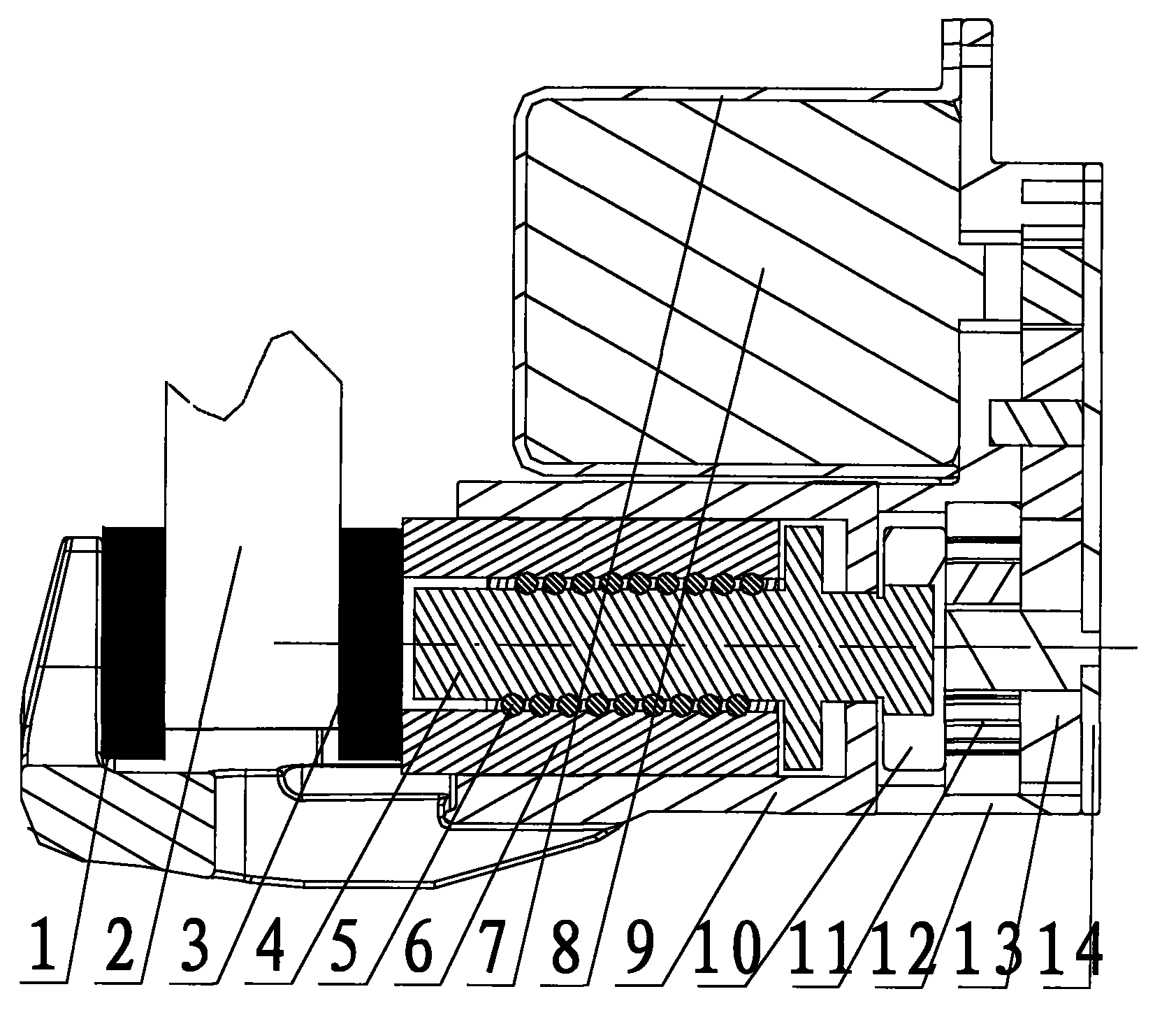
[0026] Such as figure 1 , 2 As shown, the electromechanical braking device of the present invention mainly includes an electronic control unit ECU, a power mechanism, a torque amplification mechanism, a ball screw mechanism, a friction plate 1 and a friction plate that are movable on both sides of the brake disc 2 and can clamp the brake disc. Sheet 3, and the wheel speed sensor ( figure 1 , 2 not shown).

[0027] In this embodiment, the power mechanism adopts the motor 8, and the motor 8 adopts a high-power brushless DC motor; the torque amplification mechanism adopts a reduction gear mechanism and a planetary gear mechanism connected in sequence. The reduction gear mechanism includes a plurality of reduction gears m...


PUM


Abstract

The invention provides an electronic mechanical braking device. The device comprises two friction plates (1, 3) arranged on two sides of a braking disc (2) respectively, and a braking execution mechanism which makes the two friction plates clamp the braking disc, wherein the braking execution mechanism comprises a ball screw mechanism and a power mechanism; the ball screw mechanism comprises a screw (4) and a nut (6) arranged on the screw; the screw (4) is connected with the output end of the power mechanism, and is driven to rotate by the power mechanism; and when the nut (6) on the screw makes linear motion on the screw (4), the nut (6) is contacted with the friction plate (3) arranged on one side of the braking disc. The electronic mechanical braking device has a simple and compact structure, small space occupying size and self-locking function, and can adaptively adjust the braking pressing force of the braking disc.

Description

technical field [0001] The invention belongs to the technical field of automobile wire-controlled braking in automobile manufacturing, and in particular relates to an electromechanical braking device. Background technique [0002] As consumers place increasing emphasis on vehicle safety, vehicle braking systems have undergone several changes and improvements. From the initial leather friction brake, to the appearance of drum and disc brakes, and then to the appearance of mechanical ABS braking system, followed by the development of electronic technology, analog electronic ABS braking system and digital electronic control system appeared. ABS braking system and so on. In the past 10 years, western developed countries have started to study the x-by-wire vehicle system, and then started the research on the electromechanical brake by the brake-by-wire system. Simply put, the electromechanical brake is to change the part of the brake system that was originally driven by hydraul...

Claims


Application Information

Patent Timeline
IPC IPC(8): B60T13/74
Inventor 高国兴
Owner CHERY AUTOMOBILE CO LTD
Why Eureka
Try Eureka