
Impact-free interference removal high-precision gravimetric feeder

A feeder, high-precision technology, applied in the direction of conveyors, conveyor objects, mechanical conveyors, etc., can solve problems such as reduced efficiency, inaccurate measurement, and impact on weighing accuracy, so as to achieve reduced startup and operating power, Accurate weighing results and sensitive transmission of induction

Inactive Publication Date: 2011-04-13
刘素华
View PDF7 Cites 7 Cited by
  • Summary
  • Abstract
  • Description
  • Claims
  • Application Information

AI Technical Summary

Problems solved by technology

However, due to the unreasonable structural design, there are many shortcomings. It is necessary to further improve the weighing accuracy in terms of structure and weighing methods, and reduce its own shortcomings such as easy damage and difficult maintenance. Dynamic weighing feeder and fixed weight loading device Similarly, there are the following problems: (1) The material receiving part and the weighing and reloading part are integrated. In order to prevent the material from being impacted, the whole machine is equipped with armored belts, steel tracks or thickened belts, and built-in rigid objects in the belts, etc. As a result, the weight of the feeder itself is very large, and the power consumption for starting and running is large; (2) The resource consumption of the equipment itself is large, and the failure rate is high. The whole machine needs to be disassembled during maintenance, which consumes a lot of manpower and material resources and takes up a lot of production time. (3) There is no radical anti-smashing buffer device, so that the receiving part is easily damaged by smashing, and the failure rate is high; (4) The receiving part of the integrated fuselage is impacted by materials falling from a height of tens of meters When the conveyor belt is seriously deformed, the conveyor belt sinks and pulls back, which seriously affects the weighing accuracy; (5) Due to the different materials of the belt and the armor belt, the elongation in use is different, and multiple tensions need to be increased. Changes and barriers of armor belts and steel tracks have seriously affected the stability, accuracy, and sensitivity of weighing. Due to the need for frequent tension adjustments and calibrations, it takes up a lot of production time and reduces efficiency; (6) the belt Thickening or built-in rigid objects in the belt prevent impact, making the belt too hard, hindering the gravity transmission of the material, resulting in inaccurate measurement, etc.

Method used


Image

  • Impact-free interference removal high-precision gravimetric feeder
  • Impact-free interference removal high-precision gravimetric feeder
  • Impact-free interference removal high-precision gravimetric feeder

Examples


Embodiment 1

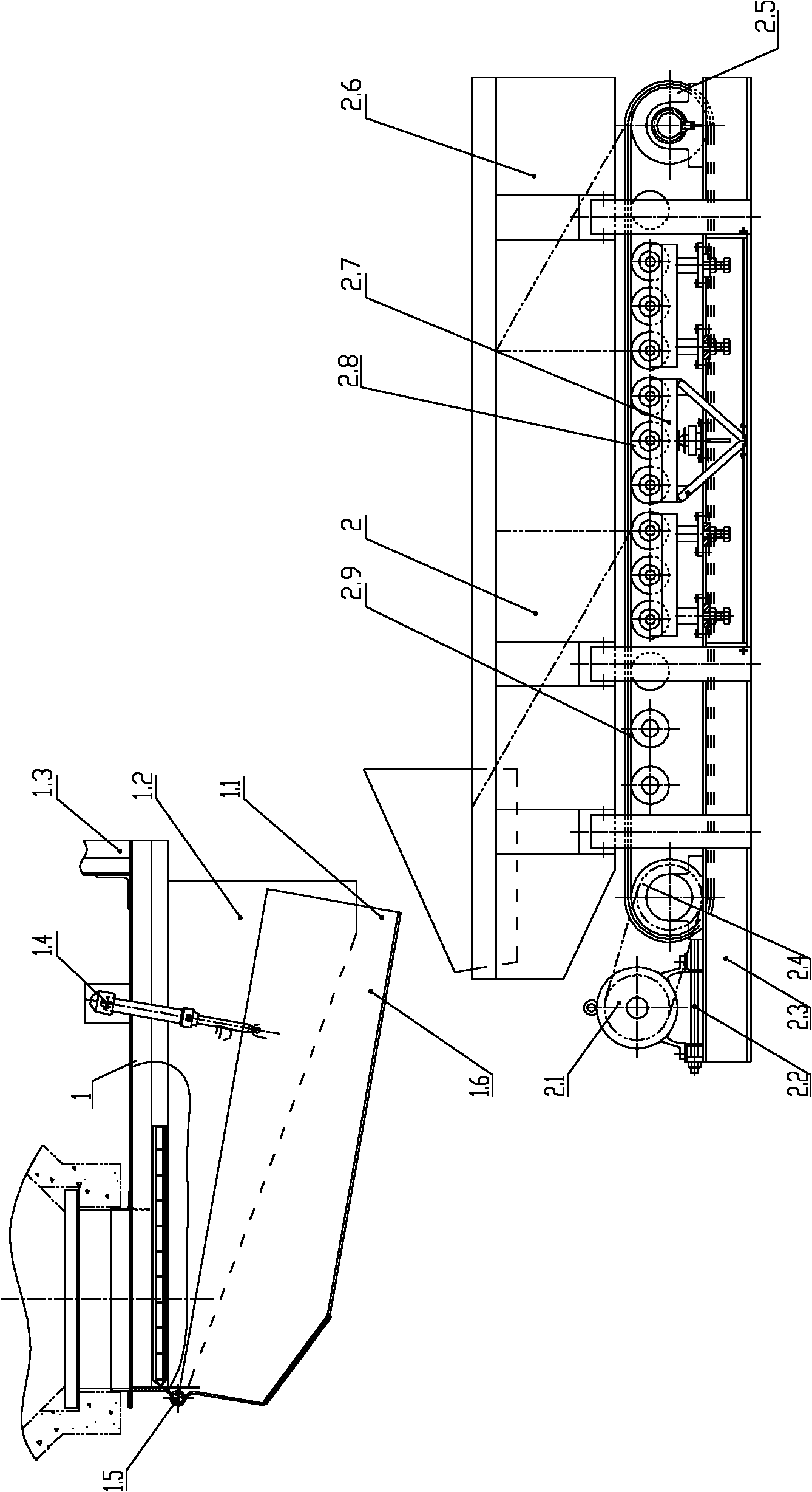
[0019] The impact-free and interference-free high-precision weight feeder includes a material receiving part 1 and a weight reloading part 2. The feeder consists of a material receiving part 1 and a reloading part 2, wherein the material receiving part 1 includes a collection hopper 1.1 and a material guide trough 1.2, and the material guide trough 1.2 is connected with the discharge port of the silo or the discharge port of other equipment. Feed trough 1.2 makes its position fixed by hanging 1.3. A variable inclination mechanism is set between the collecting hopper 1.1 and the material guide trough 1.2, such as figure 1 The hydraulic cylinder 1.4. The variable inclination mechanism can also be arranged on the bottom or side of the collecting hopper 1.1. A rotating mechanism 1.5 is provided at the joint between the collecting hopper 1.1 and the material guide groove 1.2, and the collecting hopper 1.1 can rotate along the rotating mechanism 1.5. When the material receiving p...

Embodiment 2

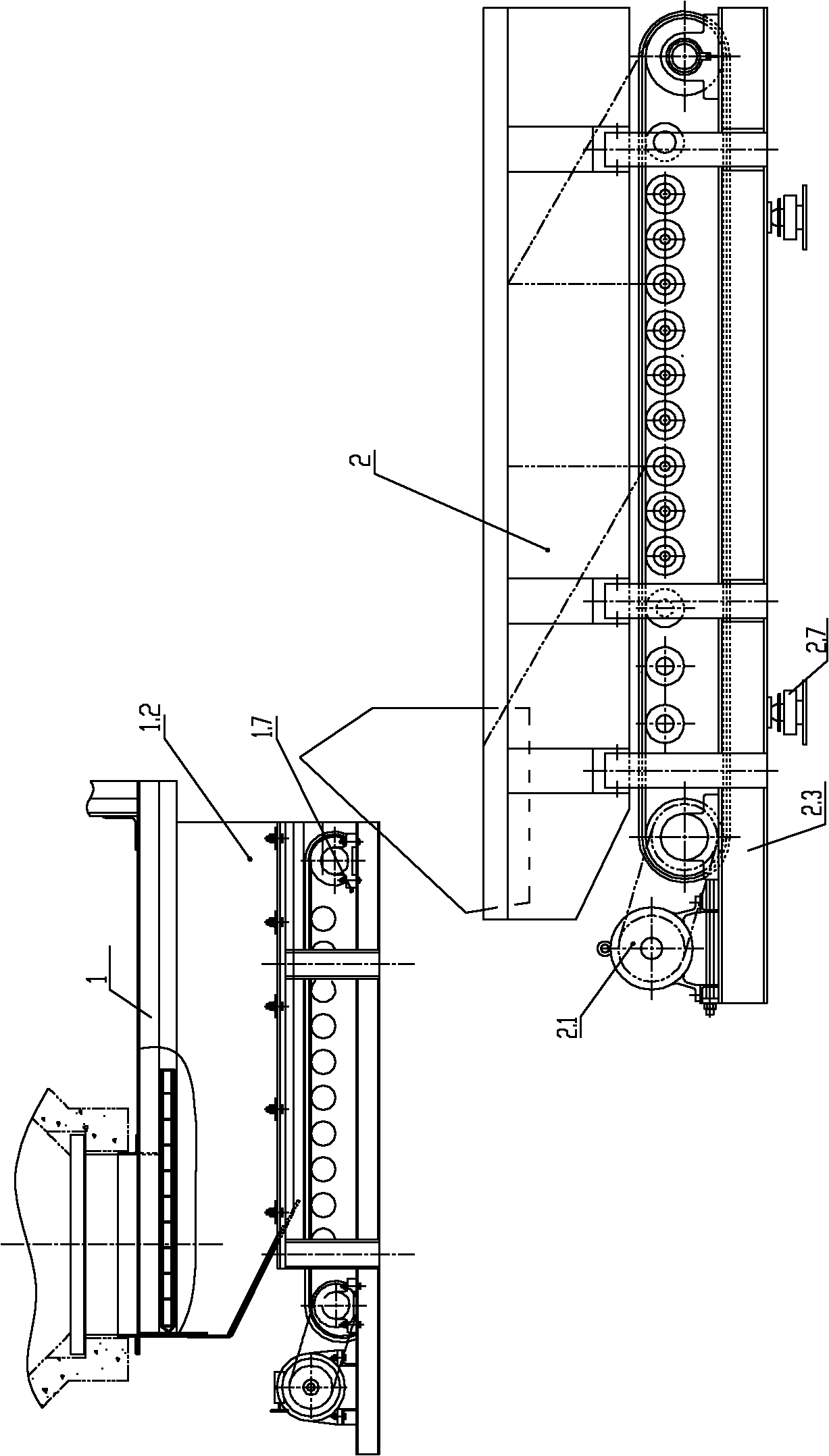
[0027] figure 2 It is the high-precision weighing feeder that avoids impact and eliminates interference described in embodiment 2. Different from Embodiment 1, the material receiving part 1 is a belt-type material receiving device, which includes a material guide 1.2 and a belt-type material receiving device 1.7, and the upper part of the material guide 1.2 is discharged from the outlet of the silo or other equipment. port connection, the bottom of the material guide trough 1.2 is connected with the belt-type material receiving device 1.7, and the material guide trough 1.2 and the belt-type material receiving device 1.7 form a box body. The belt receiving device includes a conveyor belt, driven by the conveyor belt, the material enters the reloading part.

[0028]The weighing and reloading part adopts a belt-type weighing and reloading mechanism, and the weighing sensor is set under the weighing roller and / or on the bottom surface of the reloading frame, which can be weighed...

Embodiment 3

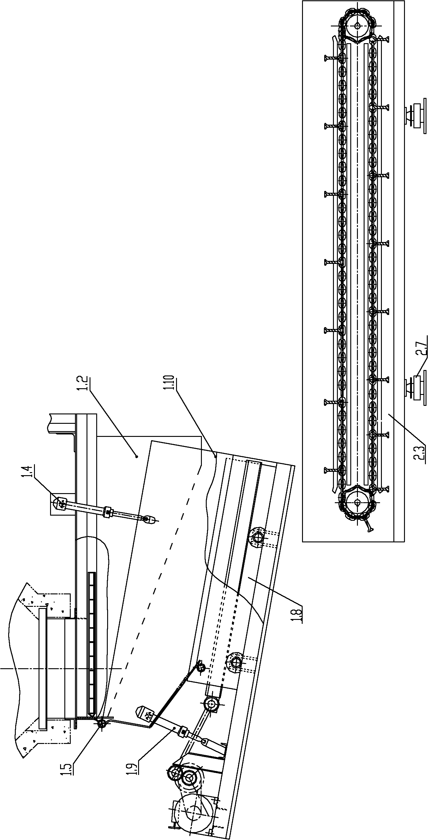
[0031] image 3 It is the high-precision weighing feeder that avoids impact and eliminates interference described in embodiment 3. The difference from Example 1 is that the material receiving part includes a collection tank 1.10, a material guide tank 1.2 and a reciprocating material receiving device 1.8, and the upper part of the material guide tank 1.2 is connected with the outlet of the silo or other equipment outlets, and the guide A variable inclination mechanism can be provided between the hopper 1.2 and the collection chute 1.10, such as image 3 The hydraulic cylinders shown, etc., are also equipped with hydraulic cylinders on the side of the collecting tank 1.10, so that the discharge port of the receiving part 1 is inclined downward at a certain angle when it is working, so that the material enters through the receiving part 1 smoothly and with the lowest drop. Weight Reproduced Part 2. The variable inclination mechanism also can adopt air cylinder, screw rod, rope...


PUM


Abstract

The invention belongs to mine, metallurgy and port equipment, and particularly relates to an impact-free interference removal high-precision gravimetric feeder. The feeder consists of a receiving part and a weighing transfer part, wherein the receiving end of the weighing transfer part is positioned at the discharge hole of the receiving part. The gravimetric feeder has reasonable and compact structure, optimized weighing mode, no interference, low fault and high precision.

Description

technical field [0001] The invention belongs to mining, metallurgy and port equipment, in particular to a high-precision weighing feeder free from impact and interference. Background technique [0002] At present, the more advanced gravimetric feeding systems in mines, metallurgy, and ports include dynamic gravimetric feeders and fixed-weight loading devices, which have been widely used in production. However, due to the unreasonable structural design, there are many shortcomings. It is necessary to further improve the weighing accuracy in terms of structure and weighing methods, and reduce its own shortcomings such as easy damage and difficult maintenance. Dynamic weighing feeder and fixed weight loading device Similarly, there are the following problems: (1) The material receiving part and the weighing and reloading part are integrated. In order to prevent the material from being impacted, the whole machine is equipped with armored belts, steel tracks or thickened belts, a...

Claims


Application Information

Patent Timeline
Patent Type & Authority Applications(China)
IPC IPC(8): B65G37/00B65G21/00B65G15/30B65G19/00B65G45/10B65G47/52G01G13/02
Inventor 刘素华
Owner 刘素华
Learn More