Yarn-raising machine

A technology of yarn kicker and yarn board, which is applied in the direction of textiles and papermaking, and can solve problems such as time-consuming and labor-intensive work, high labor intensity of workers, and damage to the bobbin yarn surface.

Active Publication Date: 2011-04-13
SHIJIAZHUANG CHANGSHAN BEIMING TECH CO LTD
View PDF5 Cites 7 Cited by
  • Summary
  • Abstract
  • Description
  • Claims
  • Application Information

AI Technical Summary

Problems solved by technology

At present, the weft winding machine mainly relies on manual doffing of the bobbin. Since the bobbin and the spindle are closely matched, a large force is required to pull out the bobbin. The doffing bobbin causes labor intensity for the workers, which is time-consuming and labor-intensive. Sometimes, due to excessive force, the neatly arranged bobbin yarn surface will be damaged, which will have an adverse effect on the next process.

Method used


Image

  • Yarn-raising machine
  • Yarn-raising machine
  • Yarn-raising machine

Examples


Embodiment Construction

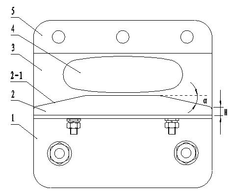
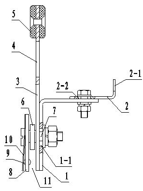
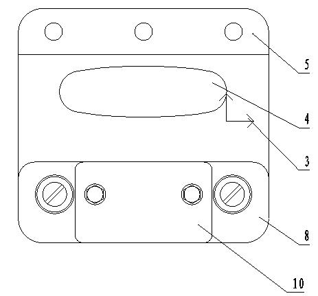
[0015] see figure 1 , figure 2 , The composition of the present invention includes a base plate 3 , a support plate 1 , a yarn raising plate 2 , a clamping plate 8 , a small shaft 7 and a bearing 6 . A handle 5 and a holding hole 4 are provided on the upper part of the base plate for holding operation. A support plate 1 is fixed on one side of the base plate, and a yarn raising board 2 is fixed on the top of the supporting board, and yarn raising slopes 2-1 are arranged on both sides of the edge of the yarn raising board; bearings 6 and clips are arranged in sequence on the other side of the supporting board A track groove 11 is formed between the plate 8, the clamping plate and the support plate. When the yarn lifting board is used to jack up the bobbin, it is placed on the track of the equipment so that the track is located in the track groove, the worker moves along the track with the yarn lifting device in hand, and the yarn lifting slope on the yarn lifting board penet...


PUM

PropertyMeasurementUnit
heightaaaaaaaaaa

Abstract

A yarn-raising machine is used to solve the problem that when the bobbin is pulled down manually, the labor intensity is high and the time and labor are greatly consumed. The technical scheme adopted by the invention is as follows: the yarn-raising machine contains a base plate, a supporting plate, a yarn-raising plate, a clamping plate, a small shaft and a bearing, wherein one side of the base plate is provided with the supporting plate, the other side of the base plate is provided with the bearing and the clamping plate in turn; a rail groove is formed between the clamping plate and the supporting plate; the yarn-raising plate is fixed with the supporting plate; and the both sides of the upper edge of the yarn-raising plate are provided with yarn-raising inclined planes. When the yarn-raising machine is used, the yarn-raising machine is placed on the rail of a spinning frame or pirn winder, the user holds the handle of the yarn-raising machine to push the yarn-raising machine to move on the rail, the bobbin can be jacked by means of the inclined planes of the yarn-raising plate, and then the bobbin can be easily pulled down. The yarn-raising machine has simple structure and is easy to realize; when the yarn-raising machine is used in a production site, the production efficiency can be effectively increased and the labor intensity can be reduced; and the disadvantage that if the bobbin is pulled down by the excessive force, the yarn surface can be damaged, is eliminated.

Description

technical field [0001] The invention relates to a textile device, in particular to a yarn lifter used for spinning bobbins such as spinning frames and weft winders after they are full of yarn, and belongs to the technical field of textile machinery. Background technique [0002] During the operation of weft winders in textile enterprises, bobbins need to be wound onto bobbins. The bobbin is driven by the spindle to rotate at a high speed. There is a cone in the inner hole of the bobbin, which is closely matched with the spindle to prevent the bobbin from being lost during rotation. When the bobbin is full of yarn, it needs to be pulled out from the spindle to replace the yarn. Tube. At present, the weft winding machine mainly relies on manual doffing of the bobbin. Since the bobbin and the spindle are closely matched, a large force is required to pull out the bobbin. The doffing bobbin causes labor intensity for workers, which is time-consuming and laborious. Sometimes...

Claims


Application Information

Patent Timeline
Patent Type & Authority Applications(China)
IPC IPC(8): D01H9/18
Inventor 朱敬尧郝郁峰刘增良吴风新徐跃红
Owner SHIJIAZHUANG CHANGSHAN BEIMING TECH CO LTD
Why Eureka
Try Eureka