Self-energizing inertia lock key type synchronizer

A self-augmenting, synchronizer technology, applied in clutches, mechanical drive clutches, transmission parts, etc., to achieve the effects of reduced ring force, good shifting feel, and simple structure

Active Publication Date: 2012-12-19
SHIYAN TONGCHUANG DRIVE TECH CO LTD
View PDF5 Cites 0 Cited by
  • Summary
  • Abstract
  • Description
  • Claims
  • Application Information

AI Technical Summary

Problems solved by technology

However, because this kind of synchronizer has relatively high requirements on materials, heat treatment and manufacturing precision, it is rarely used in China.

Method used


Image

  • Self-energizing inertia lock key type synchronizer
  • Self-energizing inertia lock key type synchronizer
  • Self-energizing inertia lock key type synchronizer

Examples


Embodiment Construction

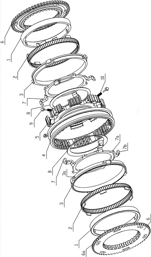
[0022] Such as figure 1 As shown, this embodiment includes double-cone synchronous ring friction components: two inner rings 1, two intermediate rings 2 and two outer rings 3; teeth meshing components: a sliding sleeve 4, a tooth seat 5 and two combined Teeth 6; pre-synchronization components: evenly distributed push blocks 9 and springs 10; double-cone synchronous ring friction components use conical surface friction to roughly synchronize the coupling teeth 6 and sliding sleeve 4, the sliding sleeve 4 enters the coupling teeth 6, and the sliding sleeve 4 is connected with the gear seat 5 by sliding splines, and also includes self-energizing components: two stamping rings 7 and two disc springs 8, and the disc springs 8 are arranged between the tooth seat 5 and the stamping ring 7;

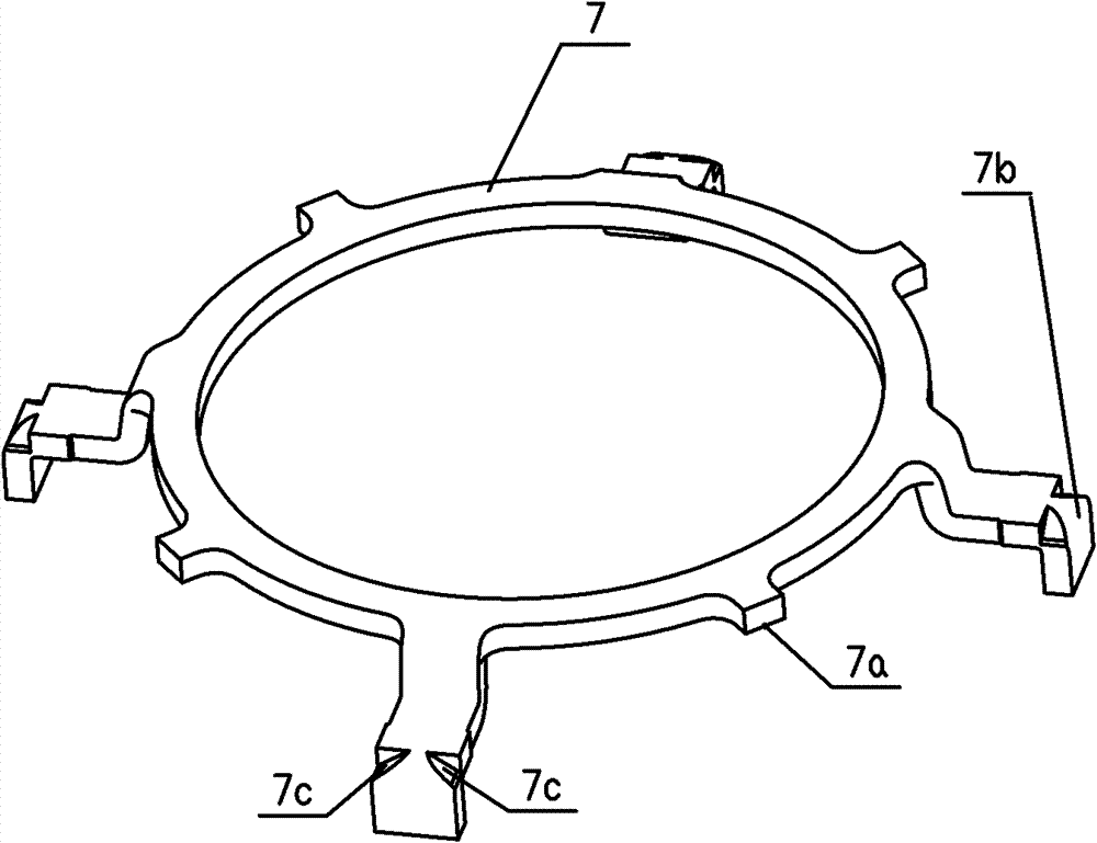
[0023] Such as figure 2 As shown, the stamping ring 7 is a ring structure with a mounting boss 7a on the outer ring, claws 7b are evenly arranged on the outer ring of the stamping ring 7, and f...


PUM


Abstract

The invention discloses a self-energizing inertia lock key type synchronizer, which comprises two inner rings, two intermediate rings, two outer rings, a sliding sleeve, gear holders, two connecting gears, pushing blocks and springs, two punched rings and two disc springs, wherein the pushing blocks and the springs are uniformly distributed and in the same number; the sliding sleeve is positionedin the connecting gears and is connected with the gear holders; the disc springs are distributed between the gear holders and the punched rings; the punched rings have a ring structure of which the outer ring is provided with a mounting boss, the outer rings of the punched rings are provided with claws uniformly; first self-energizing inclined planes are arranged on the two sides of the claws, the punched rings are inserted into the gear holders at a certain stagger angle and then arranged in a sliding sleeve, and the inner rings and the punched rings are arranged and connected through the mounting bosses; and the sliding sleeve is provided with a synchronizing gear, a second self-energizing inclined plane matched with the first self-energizing inclined planes is arranged on one side of the synchronizing gear. In the invention, the self energizing is realized by using the punched rings and the disc springs and by arranging the synchronizing gear on the sliding sleeve, the structure issimple, and the requirements on material, heat treatment and manufacturing precision are low. The synchronizer is applicable to synchronous systems for automobile gearboxes.

Description

technical field [0001] The invention relates to an automobile gearbox synchronizer, in particular to a self-energizing inertia lock ring type synchronizer. Background technique [0002] Before the present invention was proposed, the general self-energizing synchronizer was also called "Porsehe" synchronizer. The synchronizer used an open elastic synchronizer ring to replace the common tapered synchronizer ring. Its friction cone The surface is on the synchronous ring and sliding sleeve, and its structure is very different from the inertia lock ring synchronizer. However, because this kind of synchronizer has relatively high requirements on materials, heat treatment and manufacturing precision, it is rarely used in China. Contents of the invention [0003] The purpose of the present invention is to solve the shortcomings of the above-mentioned background technology, and propose a self-energizing inertia lock ring synchronizer with simple structure and low requirements on m...

Claims


Application Information

Patent Timeline
Patent Type & Authority Patents(China)
IPC IPC(8): F16D23/02F16H57/00
Inventor 万贤毅杨宏伟田军周建刘刚
Owner SHIYAN TONGCHUANG DRIVE TECH CO LTD
Why Eureka
Try Eureka