Soil source heat pump system with heat pipe heat exchanger well

A technology of soil source heat pump and heat pump system, applied in the field of soil source heat pump system, can solve the problem of water source heat pump recharge rate of less than 50%, etc., and achieve the effects of reducing extraction, small wellhead area and large heat storage volume

Inactive Publication Date: 2011-04-13
施国梁
View PDF0 Cites 4 Cited by
  • Summary
  • Abstract
  • Description
  • Claims
  • Application Information

AI Technical Summary

Problems solved by technology

[0002] Existing water source heat pump systems pump groundwater for primary use only, and the recharge rate of most water source heat pumps is less than 50%

Method used


Image

  • Soil source heat pump system with heat pipe heat exchanger well
  • Soil source heat pump system with heat pipe heat exchanger well

Examples


Embodiment Construction

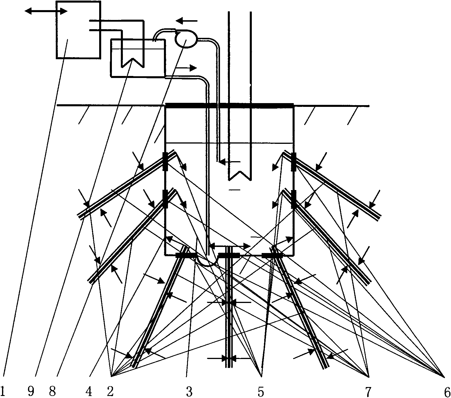
[0009] figure 1 In an embodiment, a heat pump unit 1 and a well-shaped artificial water body heat exchange well 3 with heat pipes 2 are used to form a soil source heat pump system with heat pipe heat exchange wells. Most of the heat pipes 2 arranged radially extend into the soil outside the wall 4 of the heat exchange well 3 , and the cold ends 5 of the heat pipes 2 extend into the water of the heat exchange well 3 . A rubber sealing ring 6 is lined between the heat pipe 2 passing through the well wall 4 and the well wall 4. The surface of the heat exchange well 3 and the hot end 7 of the heat pipe 2 are used as the heat exchange interface between the heat pump system and the soil, and the heat energy is conducted to the well water. The well water is pumped by the circulating pump 8 to the evaporator 9 of the heat pump unit 1 to exchange heat with the evaporator 9 and then return to the bottom of the heat exchange well 3 . The heat pump unit 1 performs work to increase the t...


PUM


Abstract

The invention relates to a soil source heat pump system with a heat pipe heat exchanging well, comprising a heat pump unit and a well-shaped artificial water body with heat pipes. The well-shaped artificial water body is also called a heat exchanging well, the surface of the heat exchanging well and the heat ends of the heat pipes are used as heat exchanging interfaces between the heat pump system and soil, the heat pump unit exchanges heat with well water in the heat exchanging well, works to output heat to the outside. For reducing continuous soil temperature fall or rise caused by heat exchange, heat-exchanging interfaces between the well water in the heat exchanging well and the outside, including interfaces between the well water in the heat exchanging well and a solar heat-collecting device or other water sources are arranged. The soil source heat pump system with the heat pipe heat exchanging well is characterized in that most parts of heat pipes in radial distribution extend into soil outside the well wall, and the cold ends of the heat pipes extend into the well water in the heat exchanging well. The invention has the advantages that the heat pipes in radial distribution has a well mouth in a small area and great effective heat-collecting capacity. The surface of the heat exchanging well and the heat ends of the heat pipes are utilized to exchange heat with soil so as to greatly reduce pumped well water or even avoid pumping well water under the condition of satisfying heat and hot water supply loads. The invention provides an embodiment shown in an attached drawing.

Description

technical field [0001] The invention relates to a soil source heat pump system with a heat pipe heat exchange well. Background technique [0002] The existing water source heat pump system extracts groundwater for primary use only, and the recharge rate of most water source heat pumps is less than 50%. In order to conserve water resources, groundwater abstraction should be minimized. Contents of the invention [0003] The purpose of the present invention is to provide a soil source heat pump system with a heat pipe heat exchange well. [0004] The technical solution adopted by the present invention to solve the technical problem is to use a heat pump unit and a well-shaped artificial water body with heat pipes to form a soil source heat pump system with heat pipe heat exchange wells. Well-shaped artificial water body is also called heat exchange well. Most of the radially arranged heat pipes extend into the soil outside the well wall, and the cold ends of the heat pipes...

Claims


Application Information

Patent Timeline
Patent Type & Authority Applications(China)
IPC IPC(8): F25B30/06F24J3/08F24J2/00
CPCY02E10/40Y02E10/10
Inventor 施国梁
Owner 施国梁
Why Eureka
Try Eureka