Micro-sensing optical unit and embedded application thereof
A sensing light and micro-technology, applied in electrical components, optical devices, instruments, etc., can solve the problems of low sensitivity and poor real-time performance of optical fiber distributed sensing, and achieve real-time response embedding technology, high sensitivity, and improved sensitivity. Effect
- Summary
- Abstract
- Description
- Claims
- Application Information
AI Technical Summary
Problems solved by technology
Method used
Image
Examples
Embodiment 1
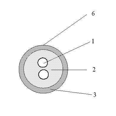
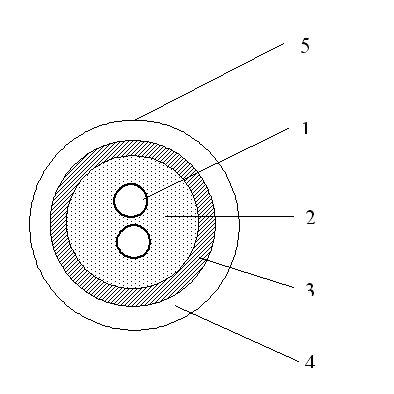
[0028] like figure 1 and 2 The micro-shaped sensing light unit shown is embedded inside or outside the cable, and it includes a micro-shaped sensing light unit body, which includes a sensing optical fiber 1, and the sensing optical fiber 1 is covered with a sealed Stainless steel tube 3, the stainless steel tube 3 is filled with water-blocking fiber paste 2; the number of optical fibers 1 for sensing is 1 or 2 or more, and the excess length of the optical fiber in the stainless steel tube 3 is within the range: 0≤excess length<0.03% . The stainless steel pipe 3 may also be coated with a sheath 4 .
[0029] The micro-shaped sensing light unit is manufactured by special equipment. The protective tube of the micro-shaped sensing light unit is usually made of a stainless steel tube 3 with a thickness of 0.15mm-0.2mm, which is formed, laser welded, and sized and drawn. Simultaneously input the sensing optical fiber 1 and the water-blocking fiber paste 2, the number of the sensin...
Embodiment 2
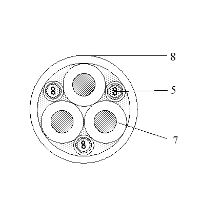
[0031] like image 3 and 4 As shown, the cable for temperature measurement using the micro-sensing light unit described in Embodiment 1, the cable includes a cable conductor core wire 7 and a cable outer sheath 8, and also includes a micro-sensing light unit, a stainless steel tube of the micro-sensing light unit 3 is wrapped with a sheath 4, and the miniature sensing light unit 5 with the sheath and the cable conductor core wire 7 are synchronously twisted inside the cable or wound outside the outer sheath 8 of the cable. In this embodiment, due to the insulation requirements of the cable, the micro-shaped sensing light unit 5 with a sheath is generally used. image 3 It is a schematic diagram of the cable structure for detecting the internal temperature of the cable. The sensing light unit 5 with a sheath can be one or more. image 3 In the middle are three sensing light units 5 with sheaths that are twisted synchronously with the cable core wires. Figure 4 It is a schem...
Embodiment 3
[0033] like Figure 5As shown, the duct optical cable that utilizes the micro-shaped sensing light unit described in Embodiment 1 for strain sensing, the duct optical cable includes a conventional communication optical unit 9 and an optical cable outer sheath 11, and also includes a miniature sensing light unit, a miniature sensing light unit Without a sheath, the miniature sensing light unit 6 without a sheath is twisted synchronously with the conventional communication light unit 9 inside the duct optical cable. The outer diameter of the micro-shaped sensing light unit 6 without a sheath fits with the clearance of the conventional communication light unit 9 , making it tangent to the circular trajectory formed by the conventional communication light unit 9 .
[0034] like Image 6 As shown, the buried optical cable that utilizes the micro-shaped sensing optical unit described in Embodiment 1 for strain sensing, the buried optical cable includes a conventional communication ...
PUM
| Property | Measurement | Unit |
|---|---|---|
| thickness | aaaaa | aaaaa |
Abstract
Description
Claims
Application Information
 - R&D
- Intellectual Property
- Life Sciences
- Materials
- Tech Scout
- Unparalleled Data Quality
- Higher Quality Content
- 60% Fewer Hallucinations
Browse by: Latest US Patents, China's latest patents, Technical Efficacy Thesaurus, Application Domain, Technology Topic, Popular Technical Reports.
© 2025 PatSnap. All rights reserved.Legal|Privacy policy|Modern Slavery Act Transparency Statement|Sitemap|About US| Contact US: help@patsnap.com


