Automatic debugging method for optical eye diagram of optical module

A technology of automatic debugging and optical modules, applied in the direction of excitation method/device, laser, laser parts, etc., can solve the problems of great influence on quality and high cost, and achieve the effect of reducing production cost

Inactive Publication Date: 2011-04-13
JIANGSU ALLRAY
View PDF0 Cites 8 Cited by
  • Summary
  • Abstract
  • Description
  • Claims
  • Application Information

AI Technical Summary

Problems solved by technology

[0004] Its disadvantages are: (1) People's subjective factors have a greater impact on quality
(2) An expensive data analyzer is required to debug and judge
(3) The cost of capacity increase is relatively high

Method used


Image

  • Automatic debugging method for optical eye diagram of optical module
  • Automatic debugging method for optical eye diagram of optical module

Examples


Embodiment Construction

[0013] Below in conjunction with accompanying drawing and specific embodiment, further illustrate the present invention, should be understood that these embodiments are only for illustrating the present invention and are not intended to limit the scope of the present invention, after having read the present invention, those skilled in the art will understand various aspects of the present invention Modifications in equivalent forms all fall within the scope defined by the appended claims of this application.

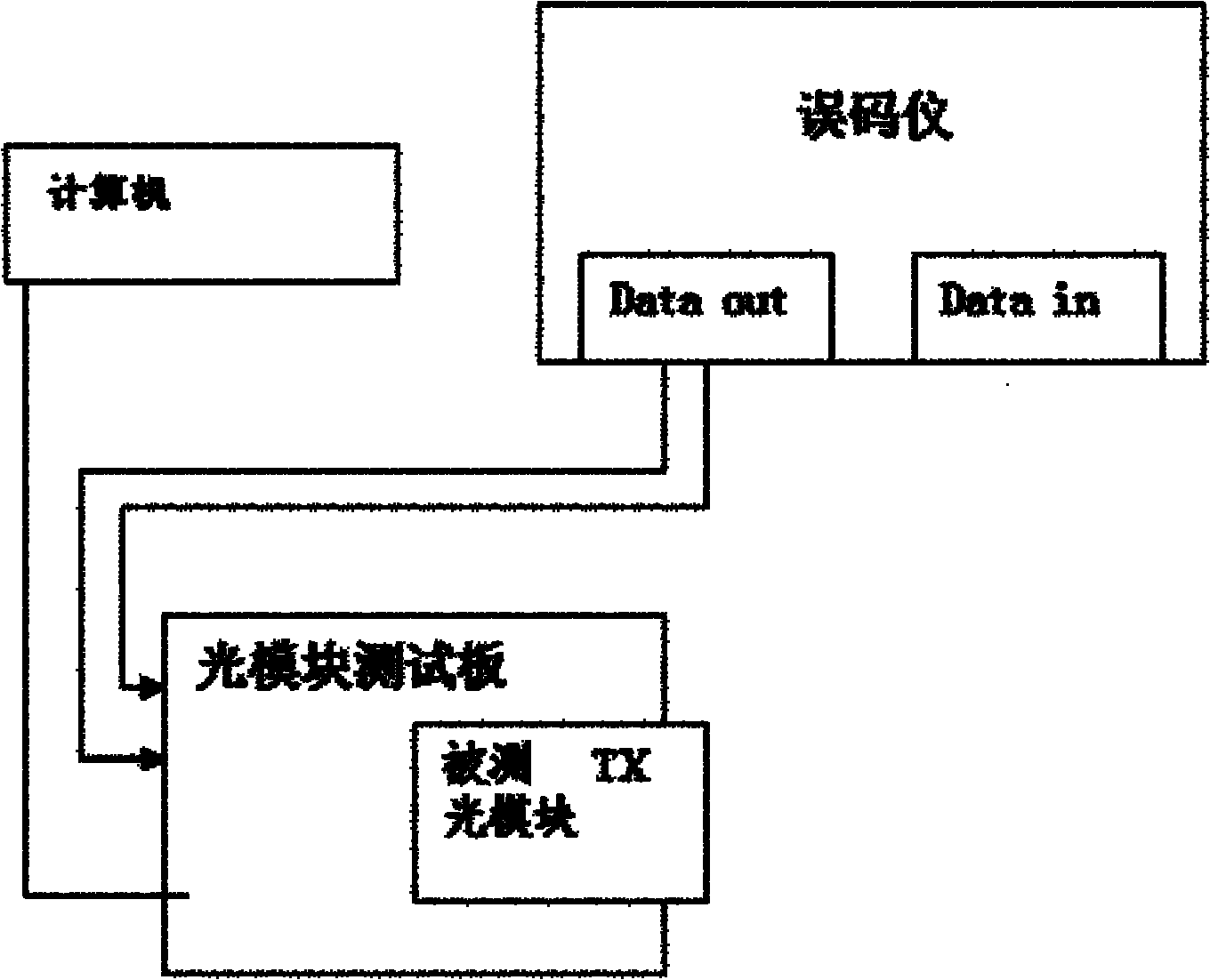
[0014] Please refer to the accompanying drawings, the present invention discloses an automatic debugging method for the optical eye diagram of an optical module. In the method, the TX optical module to be tested is connected to the optical module test board, and the test board is connected to the computer and the error code respectively. instrument.

[0015] The automatic optical eye diagram debugging method includes the following steps:

[0016] (1) First turn off the ...


PUM


Abstract

The invention provides an automatic debugging method for an optical eye diagram of an optical module. In the method, threshold current of a laser is obtained firstly and bias current of the optical module is set as the sum of the threshold current and a balance coefficient by a computer, so that the optical eye diagram is debugged automatically without artificial debugging; and Compared with the prior art, the method can prevent the influence of subjective factors of human on quality, realize debugging without using expensive data analyzers and reduce production cost simultaneously.

Description

technical field [0001] The invention relates to a debugging method, in particular to an automatic debugging method for an optical eye diagram of an optical module. Background technique [0002] The traditional method of debugging the optical eye diagram of the laser in the optical module is to use the mechanical or digital potentiometer inside the optical module to manually adjust the working point of the laser, so that the technical indicators of the optical eye diagram: extinction ratio (EXTRATIO) and cross point (CROSSING) fulfil requirements. [0003] When using the manual adjustment method, while the operator manually adjusts the value of the potentiometer, his eyes should also be fixed on the changes of the two data of the extinction ratio and the intersection point analyzed by the data communication. Because even the same batch of lasers may have different operating points. Therefore, the value of the potentiometer is also different. Sometimes it is necessary to ad...

Claims


Application Information

Patent Timeline
Patent Type & Authority Applications(China)
IPC IPC(8): H01S3/09H01S5/042
Inventor 简小忠
Owner JIANGSU ALLRAY
Why Eureka
Try Eureka