Glass substrate conveying mechanism

A conveying mechanism and glass substrate technology, applied in the direction of conveyors, conveyor objects, transportation and packaging, etc., can solve problems such as substrate quality impact, achieve the effects of reducing contact area, solving impact, and avoiding friction

Inactive Publication Date: 2017-05-31
WUHAN CHINA STAR OPTOELECTRONICS TECH CO LTD
View PDF7 Cites 8 Cited by
  • Summary
  • Abstract
  • Description
  • Claims
  • Application Information

AI Technical Summary

Problems solved by technology

[0004] In order to overcome the deficiencies of the prior art, the present invention provides a glass substrate conveying mechanism, thereby preventing scratches on the surface of the substrate during conveying, and solving the influence of the existing roller conveying equipment on the quality of the substrate

Method used


Image

  • Glass substrate conveying mechanism
  • Glass substrate conveying mechanism
  • Glass substrate conveying mechanism

Examples


Embodiment Construction

[0020] The present invention will be described in further detail below in conjunction with the accompanying drawings and embodiments.

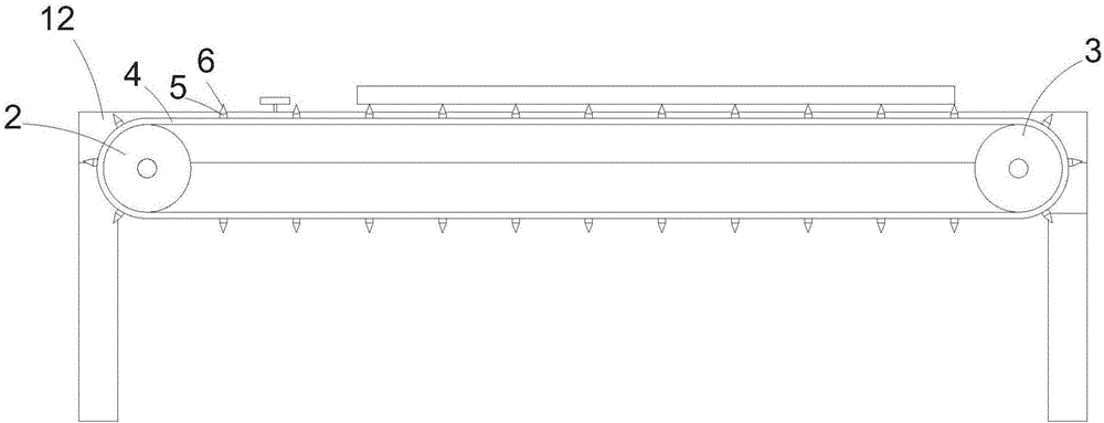
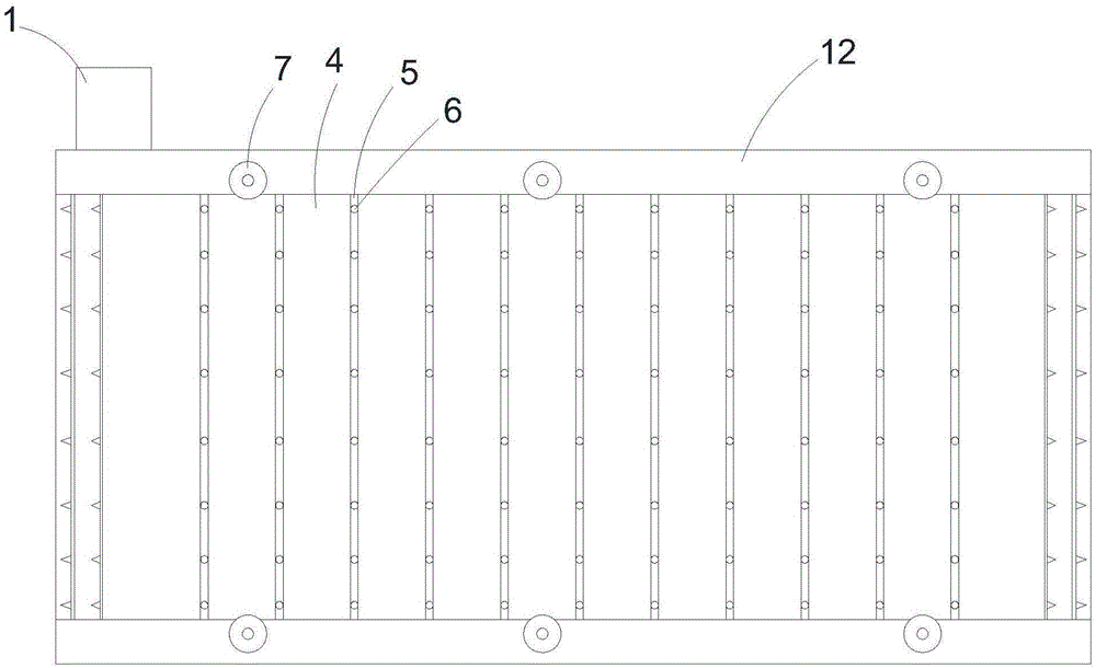
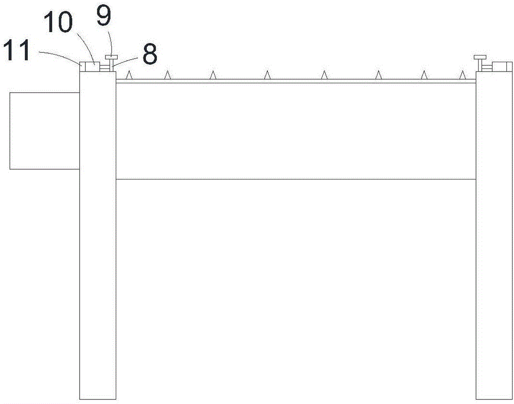
[0021] Such as figure 1 , figure 2 As shown, a glass substrate conveying mechanism of the present invention includes a frame 12 erected between the equipment used in each processing process, and a conveying mechanism is provided on the frame 12. Sent to the next process equipment, in the present invention, the conveying mechanism includes an O-shaped conveyor belt 4, the surface of the conveyor belt 4 is evenly distributed with reinforcing ribs 5, and the upper end of the reinforcing ribs 5 is higher than the surface of the conveyor belt 4, so that the reinforced There is a drop between the ribs 5 and the conveyor belt 4 , so that the reinforcing ribs 5 can carry the glass substrate and reduce the contact area between the glass substrate and the conveyor belt 4 .

[0022] Specifically, the reinforcing ribs 5 are arranged along the width dir...


PUM


Abstract

The invention provides a glass substrate conveying mechanism which comprises a conveying mechanism, wherein the conveying mechanism comprises an O-shaped conveyer belt; and reinforcing ribs are uniformly distributed on the surface of the conveyer belt. Compared with the prior art, the glass substrate conveying mechanism has the effects that the reinforcing ribs are arranged on the surface of the conveyer belt, the contact area of a substrate and the conveyer belt is reduced, the friction between the conveyer belt and the substrate is avoided, and thus the influence of conventional conveying equipment to substrate product quality can be effectively solved.

Description

technical field [0001] The invention relates to a liquid crystal panel production technology, in particular to a glass substrate conveying mechanism. Background technique [0002] The existing CF substrate (color film filter) processing process includes substrate cleaning, coating, inspection, exposure, development, inspection, baking, and cooling, so the substrate needs to be flown and transported in each equipment for processing. [0003] The existing substrate conveying mechanism is designed as a combination of robot arm conveying and roller conveying. The roller conveying method is to distribute rollers at intervals on the rotating shaft, and the upper substrate is driven by the rotation of the rollers. The guide roller (guide roller) functions to keep the substrate moving. The direction is stable. Since the back of the substrate is in direct contact with the roller and friction will occur, it is easy to cause scratches on the back of the substrate or roller marks, which...

Claims


Application Information

Patent Timeline
Patent Type & Authority Applications(China)
IPC IPC(8): B65G49/06B65G15/30
CPCB65G15/30B65G49/063
Inventor 史朋超
Owner WUHAN CHINA STAR OPTOELECTRONICS TECH CO LTD
Why Eureka
Try Eureka