Laser machining tool having expanded work space

A technology of laser processing machine and laser processing head, which is applied in the direction of laser welding equipment, metal processing equipment, manufacturing tools, etc., to achieve the effect of reducing space requirements and high synchronization

Active Publication Date: 2011-04-13
TRUMPF WERKZEUGMASCHINEN GMBH & CO KG
View PDF7 Cites 11 Cited by
  • Summary
  • Abstract
  • Description
  • Claims
  • Application Information

AI Technical Summary

Problems solved by technology

Only workpieces that are much smaller than the base of the laser processing machine c

Method used


Image

  • Laser machining tool having expanded work space
  • Laser machining tool having expanded work space
  • Laser machining tool having expanded work space

Examples


Embodiment Construction

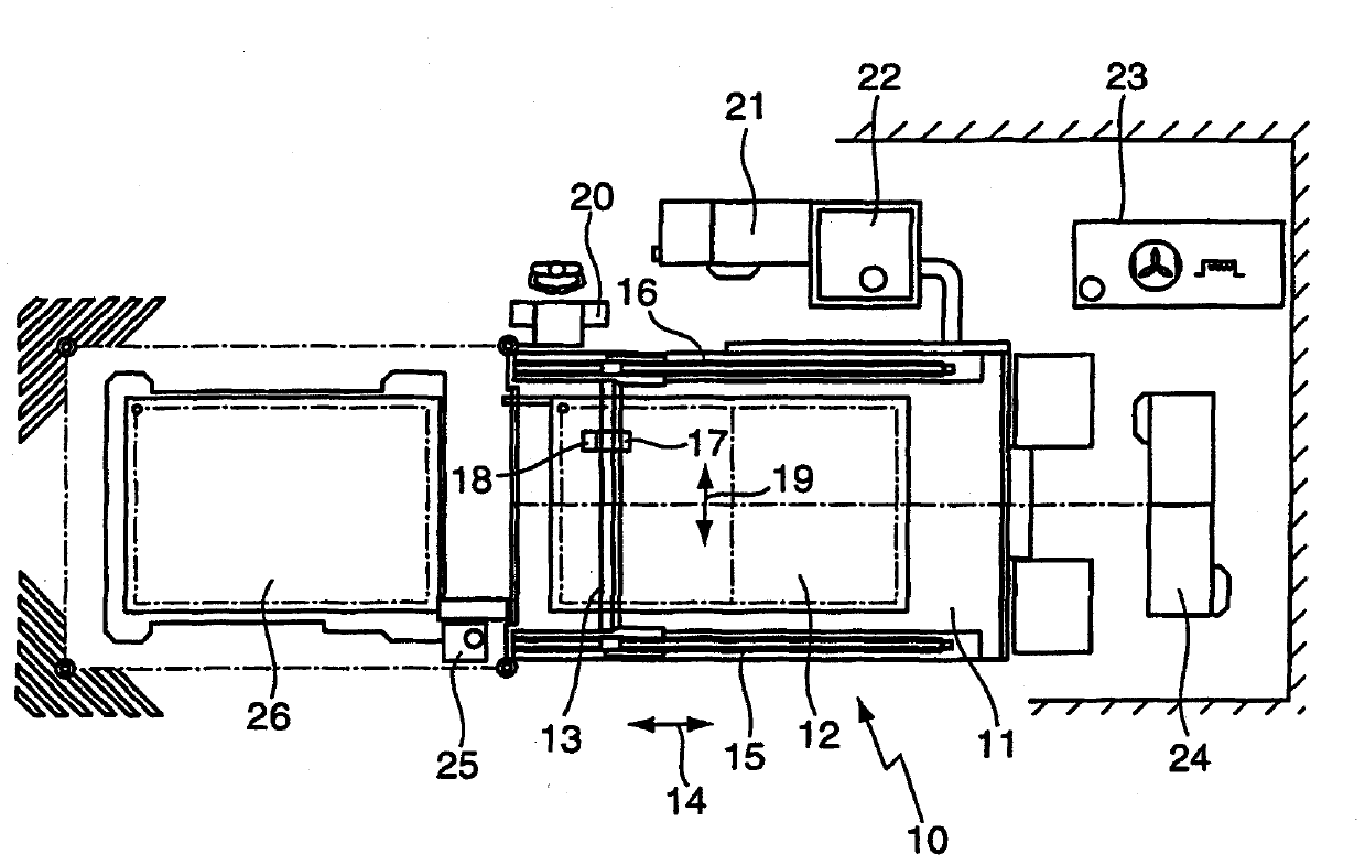
[0035] figure 1 A laser processing machine 10 is shown with a workpiece holder 11 on which a workpiece 12 is arranged. A support structure 13 in the form of a gantry is arranged above the workpiece 12 . The support structure 13 is movable along the guides 15 , 16 in the direction of the double arrow 14 . Here, the carrier structure 13 is driven by a linear drive. The device causing the movement in the direction of the double arrow 14 is called the (tool) shaft. Laser processing heads 17 , 18 are arranged on both sides of the carrier structure 13 . The laser machining head is movable relative to the carrier structure 13 in the direction of the double arrow 19 . The device which brings about the movement in the direction of the double arrow 19 is likewise called the (tool) shaft. Since the laser processing heads 17 , 18 are arranged on both sides of the carrier structure, a maximum working area is achieved. In particular, workpieces can be machined which have substantially...


PUM


Abstract

On a laser machining tool (10) having a supporting structure (13), on the one side of which at least one laser machining head (17, 18) is arranged, and further having a tool holder and/or tool support (11), wherein the laser machining head (17, 18) and the tool holder and/or tool support (11) can be moved relatively to each other, at least one laser machining head (17, 18) is arranged on two opposing sides of the supporting structure (13). A beam switch is provided, by which a laser beam can be switched between the laser machining heads. Thus, the work space can be enlarged.

Description

technical field [0001] The invention relates to a laser processing machine with a carrier structure and a workpiece holding device and / or a workpiece support, at least one laser processing head is arranged on one side of the carrier structure, wherein the laser processing head and the workpiece holding device And / or the workpiece holders are movable relative to each other. Background technique [0002] A laser processing machine is known, for example, from JP 03-138092A, in which the workpiece to be processed is placed on a workpiece holder. A gantry may be arranged above the workpiece support in the longitudinal direction of the workpiece. A laser processing head can be arranged on one side of the gantry, which can be moved relative to the workpiece by the movement of the gantry. Workpieces can be processed with the aid of the laser processing head. Only workpieces that are much smaller than the base of the laser processing machine can be processed with the described kno...

Claims


Application Information

Patent Timeline
IPC IPC(8): B23K26/06B23K26/067B23K26/08B23K26/10
CPCB23K26/0673B23K26/10B23K26/083B23K26/0604B23K26/0869B23K26/067
Inventor A·克特纳-赖希
Owner TRUMPF WERKZEUGMASCHINEN GMBH & CO KG
Why Eureka
Try Eureka