High frequency waveguide, antenna device, and electronic apparatus with antenna device

An antenna device and high-frequency wave technology, which is applied to the field of antenna devices and electronic equipment using them, and high-frequency waveguides, and can solve the problems of large antenna devices, unoptimized antenna devices, and large antenna devices.

Inactive Publication Date: 2011-04-13
PANASONIC CORP
View PDF6 Cites 7 Cited by
  • Summary
  • Abstract
  • Description
  • Claims
  • Application Information

AI Technical Summary

Problems solved by technology

In addition, in order to make the structure that drives the large antenna body to the left and right, the movable space is also included, and as a result, the antenna device becomes very large.
[0013] In recent automobiles, for example, energy-saving measures and the like have been sought to be compact. In this system, although it is a safety measure, the antenna device becomes large and is not preferable.

Method used


Image

  • High frequency waveguide, antenna device, and electronic apparatus with antenna device
  • High frequency waveguide, antenna device, and electronic apparatus with antenna device
  • High frequency waveguide, antenna device, and electronic apparatus with antenna device

Examples


Embodiment approach

[0133] Hereinafter, an embodiment of the present invention will be described by citing an example used in an automobile as an electronic device equipped with an antenna device 6 including a high-frequency waveguide, for example.

Embodiment approach 1

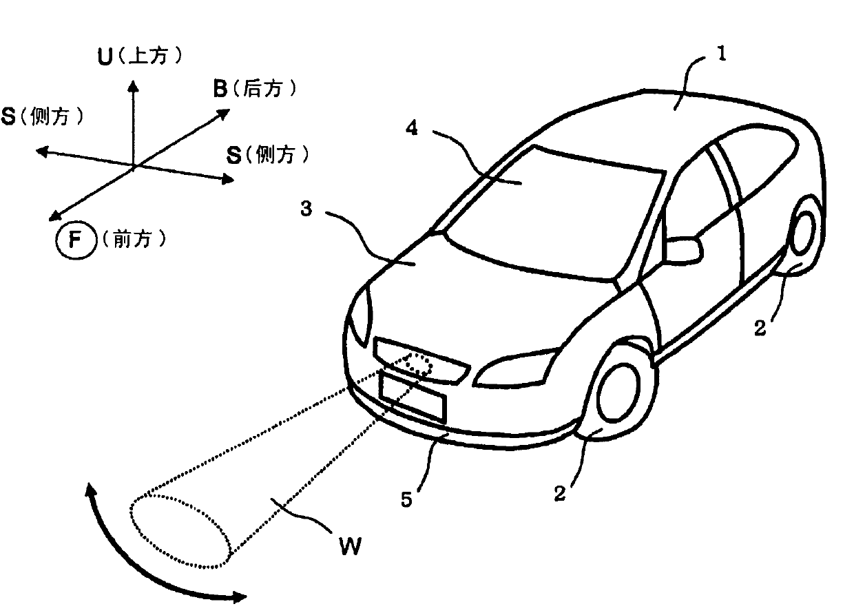
[0135] figure 1 Among them, 1 is a car body, and 2 is four tires provided under the car body 1 .

[0136] These tires 2 are rotationally driven by an engine (not shown) housed under the hood 3 of the vehicle body 1 .

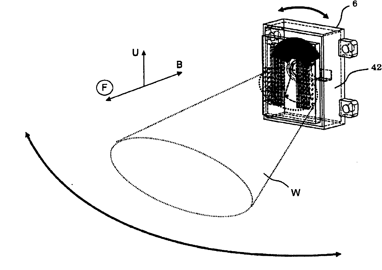
[0137] In addition, a steering wheel (not shown) for driving the tires 2 is provided in the interior 4 of the vehicle main body 1 . In addition, above the bumper 5 on the front side of the vehicle body 1, a figure 2 Antenna assembly 6 is shown.

[0138] The antenna unit 6 will be described in detail later, but as these figure 1 , figure 2 As shown, in the front side of the automobile body 1, with respect to the front (for example, within a range of 150 meters), the horizontal direction from the center is at a predetermined angle (for example, 15 degrees in the left and right (a total of 30 degrees) range), the 76.5GHz radio wave W scans its angle sequentially and emits it. And, it receives the reflected wave within 150 meters from the front in the irradi...

Embodiment approach 2

[0233] For the antenna device 206 according to another embodiment of the present invention, use Figure 25 ~ Figure 31 The description is as follows.

[0234] In addition, the main configuration of the antenna device 206 according to the present embodiment is the same as that of the antenna device 6 according to the above-mentioned first embodiment, and only the points of difference will be extracted and described here. In addition, in this embodiment, for the convenience of description, the same reference numerals are attached to members having the same functions as those in Embodiment 1 above, and descriptions thereof are omitted.

[0235] The antenna device 206 of this embodiment is the same as the antenna device 6 of the above-mentioned first embodiment, and is mounted on figure 1 In the vicinity of the front central part of the car body 1 shown, from the front face relative to the range of about 150 meters ahead, from the center to the horizontal direction along the left...


PUM


Abstract

A waveguide structure (8) includes a movable waveguide body (10) and a fixed waveguide body (12) opposed to the movable waveguide body (10) at a predetermined distance apart. At least the movable waveguide body or the fixed waveguide body, a groove or grooves (13, 29) are formed in the opposite surfaces of the waveguide bodies. Outside at least one of the grooves (13, 29), projections (44) having a height of approximate Lambada/4 (Lambada is the wavelength of the electromagnetic wave used) are provided.

Description

technical field [0001] The present invention relates to a high-frequency waveguide, an antenna device, and an electronic device using the same. Background technique [0002] A high-frequency waveguide used as a path for radio waves is composed of a combination of first and second waveguide structures. [0003] Specifically, the first and second waveguide structures respectively provided with grooves are integrated in a state where the openings of the grooves correspond to each other, thereby constituting a high-frequency waveguide. In addition, there is the following Patent Document 1 among conventional documents similar to this. [0004] In addition, in recent years, radar devices used for collision avoidance, inter-vehicle distance control, and the like have been installed in automobiles. This radar device requires a detection angle of about 15 degrees left and right (30 degrees in total) in order to be able to measure even when the car is traveling on a curve. [0005]...

Claims


Application Information

Patent Timeline
Patent Type & Authority Applications(China)
IPC IPC(8): H01P1/06G01S7/03G01S13/93H01P1/04H01Q3/32G01S13/931
CPCG01S13/931H01Q1/3233H01P1/068H01Q3/06G01S2013/9321G01S2013/9375G01S2013/9325G01S7/032G01S2013/93271G01S7/027
Inventor 桐野秀树渡部昌史山本功
Owner PANASONIC CORP
Why Eureka
Try Eureka