
Oil-water automatic separator

An oil-water separation tank, oil-water technology, applied in the direction of immiscible liquid separation, etc., to reduce environmental pollution, reduce production costs, and achieve good results

Inactive Publication Date: 2011-04-20
YANCHENG ZHONGJI INDAL AUTOMATION ENG
View PDF0 Cites 4 Cited by
  • Summary
  • Abstract
  • Description
  • Claims
  • Application Information

AI Technical Summary

Problems solved by technology

Scientific researchers in the same industry continue to study and explore oil-water separation technology, improve production process, and increase oil-water separation rate. Although they have achieved certain results, there are still technical problems that have not been overcome in practical applications.

Method used


Image

  • Oil-water automatic separator
  • Oil-water automatic separator

Examples


Embodiment Construction

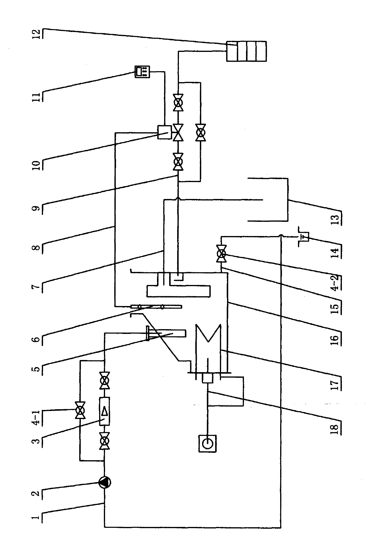
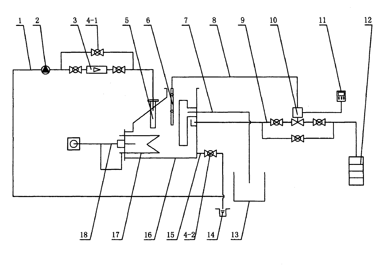
[0010] In the picture: the water pipe 1 is a hollow pipe made of metal. The water pipe 1 is equipped with a water pump 2 and a flow meter 3. There are valves on the left and right sides of the flow meter 3, and the two ends of the valve 4-1 extend out of the pipe Connect to the water pipe 1, sandwich the valves on the left and right sides of the flow meter 3, and connect the water pipe 1 to the degreasing tank 13. One end of the signal line 8 is connected to the oil level sensor 6, and the other end is connected to the electric regulating valve 10. There is a valve on the left and right sides of the electric regulating valve 10. A valve is arranged on the lower top of the electric regulating valve 10, and a valve is on the right end. The drain pipe 9 is connected to the oil collecting barrel 12, and the valve at the left end is connected to the middle end of the oil-water separation tank 16 through the oil drain pipe 9. The upper end of the oil-water separation tank 16 is provid...


PUM


Abstract

The invention relates to an oil-water automatic separator which comprises a water pipe, a water pump, a flowmeter, a valve, an liquid inlet, an oil level sensor, a return pipe, a signal wire, an oil discharge pipe, an electric adjustment valve, a program control box, an oil collecting barrel, a degreasing tank, a sewage discharge pond, a discharge pipe, an oil-water separating tank, a heater and a temperature sensor. A computer closed loop technology is adopted so that the oil-water automatic separator is controlled by a set oil-water automatic separation program. In the oil-water separating tank, heated emulsified oil floats on water surface, the oil level sensor sends an electric signal to the electric adjustment valve, and the electric adjustment valve is opened for discharging effluent oil into the oil collecting barrel; when the discharged oil reaches a set lower limit, the oil level sensor sends another electric signal, the electric adjustment valve closes automatically, the treated degreased oil returns to the degreasing tank from the oil-water separating tank through the return pipe, and a valve (4-2) is opened so that sewage in the oil-water separating tank flows into the sewage discharge pond to be purified. The oil-water automatic separator can save energy, protect the environment, reduce environmental pollution and production cost and achieve good oil-water separation effect.

Description

Technical field [0001] The invention relates to a coating oil-water separation equipment, in particular to an automatic oil-water separator. Background technique [0002] Environmental pollution has attracted the attention of governments all over the world, and it is related to the survival of human beings, animals and plants. The Chinese government has incorporated energy conservation and emission reduction into its national policy. With the reform and opening up, my country's industry is developing rapidly, especially the surface treatment of steel and other products with more and more chemicals, which has brought industrial pollution. Especially in the chemical industry, during the degreasing process, the anti-rust oil, drawing oil, motor oil, and most of the animal and vegetable oils are emulsified in the degreasing liquid by the surfactant in the degreasing liquid (oil-water Mixture), when their content is too high, it will directly affect the subsequent degreasing effect....

Claims


Application Information

Patent Timeline
IPC IPC(8): B01D17/02
Inventor 王文江蔡志祥蔡高峰陈玉林陈海勇
Owner YANCHENG ZHONGJI INDAL AUTOMATION ENG
Learn More