Floating unloading type device for loosening blade on main shaft

A spindle and tool loosening technology, which is applied in the direction of positioning device, clamping, support, etc., can solve the problems of affecting, reducing the accuracy of the spindle and service life, etc., and achieve the effect of simple overall structure and prolonging service life

Inactive Publication Date: 2011-04-20
CHENGDU PRECISE CNC MACHINE TOOL
View PDF4 Cites 4 Cited by
  • Summary
  • Abstract
  • Description
  • Claims
  • Application Information

AI Technical Summary

Problems solved by technology

[0003] However, during the use of this automatic tool loosening device at present, because the piston rod of the pressurized cylinder moves downward quickly under the action of external pressure, it will generate a relatively large impact force when it touches the main shaft broach rod, and the impact force It will directly act on the main shaft and the main shaft support bearing; at the same time, because the piston rod of the booster cylinder will continue to move downward under inertia, thereby compressing the disc spring set on the main shaft broach rod, it will eventually be about 4500kgf or The tool release force of 6000kgf all acts on the supporting bearing of the main shaft, so it will seriously affect and reduce the accuracy and service life of the main shaft

Method used


Image

  • Floating unloading type device for loosening blade on main shaft
  • Floating unloading type device for loosening blade on main shaft
  • Floating unloading type device for loosening blade on main shaft

Examples


Embodiment

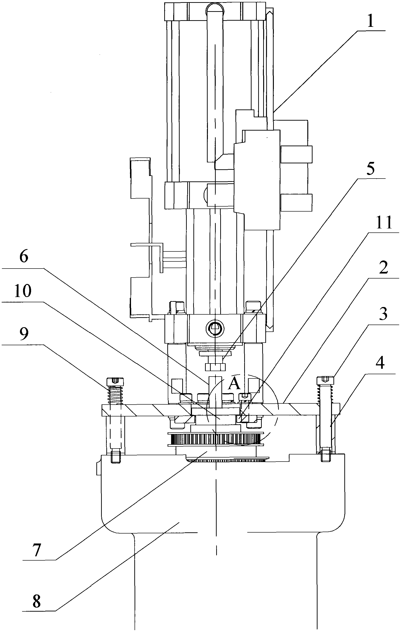
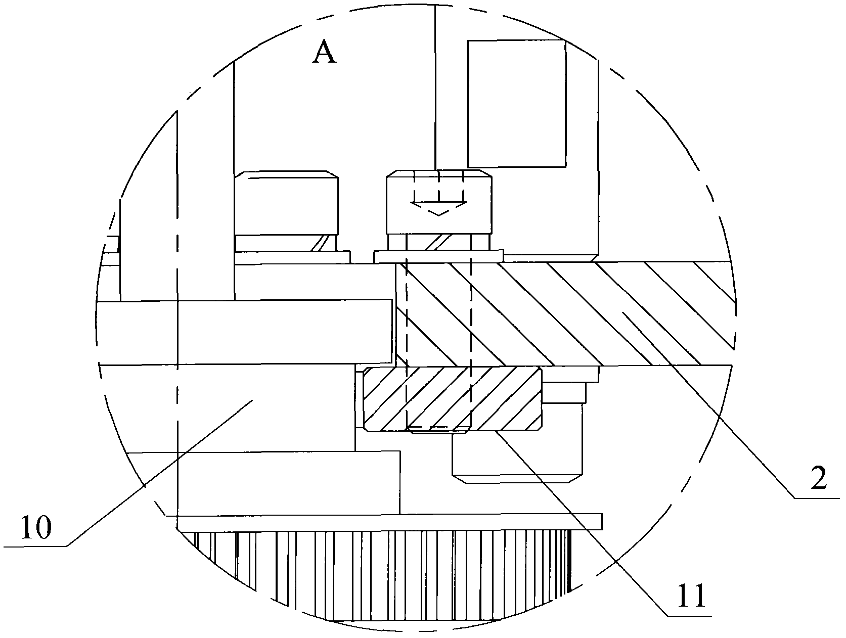
[0018] like figure 1 , 2 As shown, the pressurized cylinder 1 of the present invention is provided with a pressurized cylinder piston rod 5 that can freely expand and contract along the vertical direction, and the interior of the main shaft housing 8 is equipped with a freely rotatable main shaft 7 . The broach rod 6 used for grasping and releasing the tool is arranged inside the main shaft 7, and can move up and down along the central axis of the main shaft 7 to compress and relax the butterfly spring. The end of the broach rod 6 corresponding to the booster cylinder piston rod 5 protrudes outside the spindle housing 8, and the central axis of the broach rod 6 is on the same line as the central axis of the booster cylinder piston rod 5. On a straight line, to ensure that the broach bar 6 can be right at the end of the broach bar 6 when moving down quickly.

[0019] A booster cylinder load-bearing plate 2 is also fixed by screws on the booster cylinder 1, which ensures that ...


PUM


Abstract

The invention discloses a floating unloading type device for loosening blade on main shaft, which mainly comprises: a headstock body (8) with a main shaft (7) inside, a broach rod (6) which is arranged inside the main shaft (7) and is movable up and down along the center line of the main shaft, a pressure cylinder (1) fixedly connected with a pressure cylinder bearing plate (2), sleeves (4) arranged between the pressure cylinder bearing plate (2) and the headstock body (8). Guiding bolts (3) arranged on the pressure cylinder bearing plate (2) traverse sleeves (4) and are fixedly connected with the headstock body (8). The invention is characterized in that: the screws of the guiding bolts (3) are sleeved with elastic components (9) for the buffer actions between the guiding bolt (3) cap heads and the pressure cylinder bearing plate (2). The invention has a simple overall structure, and can carry out an effective buffer against generated impact force, thereby greatly reduces the influence caused by impact force to the broach rod, consequently prolongs usage life.

Description

technical field [0001] The invention relates to a tool release device, in particular to a floating and unloading spindle tool release device. Background technique [0002] The automatic loosening and broaching action of the CNC machine tool spindle is an indispensable function in machine tool processing. At present, the tool loosening action of the CNC machine tool spindle is realized by the automatic tool releasing device. Only after the action can the tool on the main shaft be removed, and after the main shaft is replaced with a new tool, the broaching action is performed, and the tool on the main shaft can only be processed after being tightened. When the current machine tools change the tool for the main shaft, the usual structure is to first push the tool pull rod with the disc spring through the action of the tool release cylinder, so that the chuck of the machine tool holding the tool is released to perform the tool release action. ;When a new tool is replaced on the...

Claims


Application Information

Patent Timeline
IPC IPC(8): B23Q3/157
Inventor 肖红莫春林梁吉平金志钢李知密李青
Owner CHENGDU PRECISE CNC MACHINE TOOL
Why Eureka
Try Eureka