Electric power tool

A technology for power tools and circuit boards, which is applied in the direction of manufacturing tools, power components, electrical components, etc., can solve problems such as short circuits, and achieve the effect of improving heat dissipation efficiency

Active Publication Date: 2011-04-20
PANASONIC CORP
View PDF7 Cites 8 Cited by
  • Summary
  • Abstract
  • Description
  • Claims
  • Application Information

AI Technical Summary

Problems solved by technology

In other words, an increase in the amount of air introduced through the air supply-exhaust holes may lead to an increased possibility of short circuits due to iron particles or water droplets present in the cited air

Method used


Image

  • Electric power tool
  • Electric power tool
  • Electric power tool

Examples


Embodiment Construction

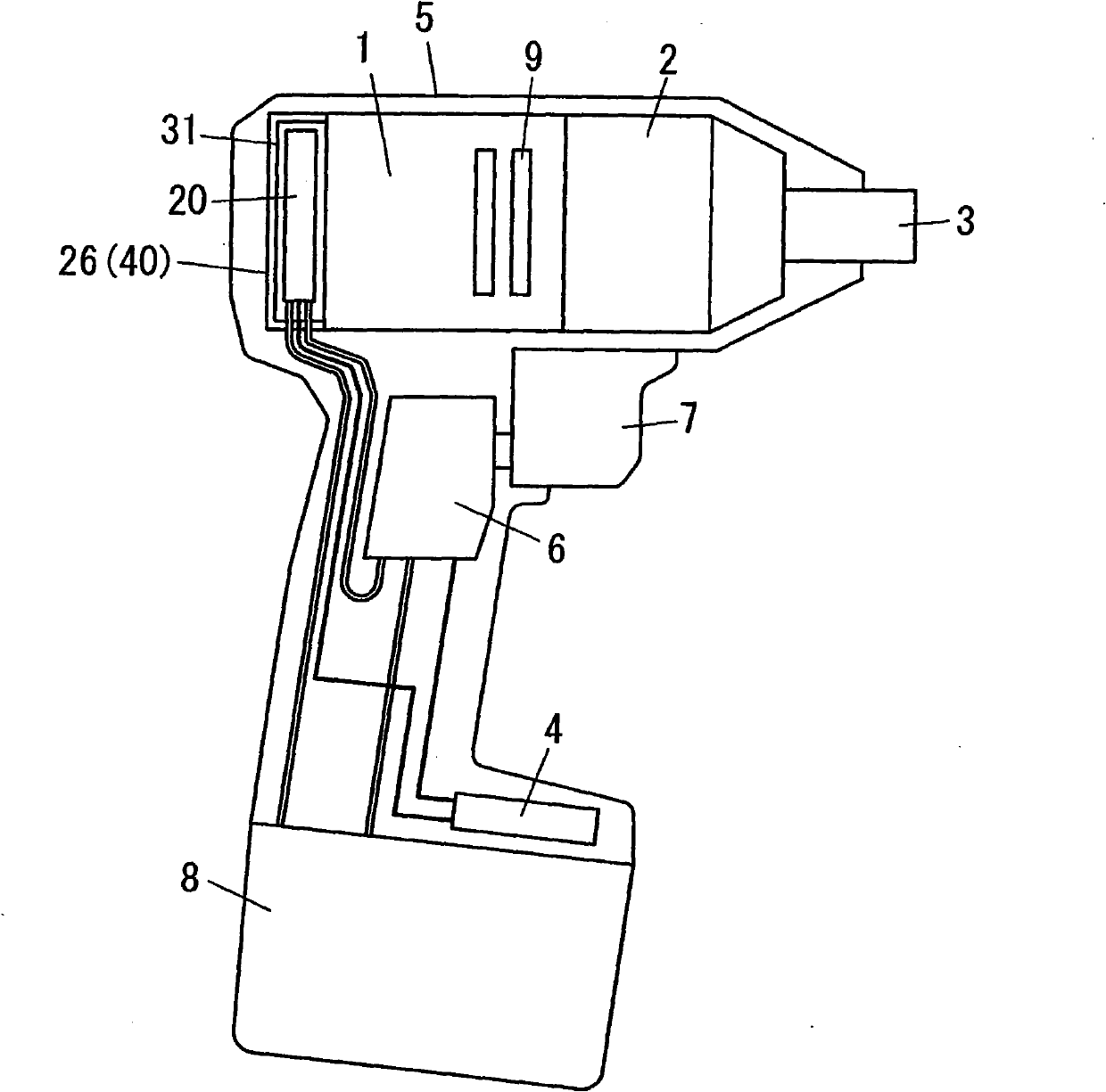
[0022] Embodiments of the present invention are described below with reference to the accompanying drawings forming a part of the present invention. figure 1 The overall configuration of an electric power tool according to one embodiment of the present invention is schematically shown.

[0023] The electric tool is a hand-held electric rotary tool, which includes a housing 5, a motor 1 used as a driving power source, a reduction mechanism 2 for transmitting the power of the motor 1, and a power output driven by the power transmitted through the reduction mechanism 2. Unit 3. The motor 1 , the reduction mechanism 2 , and the power output unit 3 are connected in series in the casing 5 . The housing 5 has air supply-exhaust holes 9 opened in the vicinity of the motor 1 . In this specification, the side to which power is transmitted (i.e., the side where the reduction mechanism 2 is located relative to the motor 1) is referred to as the "front side", and the opposite side (i.e.,...


PUM


Abstract

An electric power tool includes a motor, a speed reduction mechanism, a power output unit, a control circuit unit, and a housing. The housing provided with an air supply-exhaust hole. The motor includes a stator core wound with coils, a rotor core and an electronic circuit unit. The electronic circuit unit includes a circuit board, electronic components arranged in the circuit board and including a switching element, coil connection portions arranged in the circuit board and connected to the coils and a control circuit connection portion arranged in the circuit board and connected to the control circuit unit. The motor further includes a radiator member for dissipating heat generated in the switching element of the electronic circuit unit and an insulating cover member molded to cover the electronic components, the coil connection portions, the control circuit connection portion, the circuit board and the radiator member.

Description

technical field [0001] The invention relates to an electric tool using a brushless motor. Background technique [0002] In an electric tool using a brushless motor, a structure is required to effectively cool the motor and switching elements, both of which tend to become hot during operation. Japanese Patent Application Publication No. 2009-72880 discloses a brushless motor in which a heat sink is in contact with a switching element to dissipate heat generated from the switching element. [0003] However, in a conventional brushless motor, electronic parts, such as switching elements, etc., and their connection parts are arranged on a circuit board in an exposed state. If a brushless motor is used in a power tool, iron particles or water droplets present in the air may adhere to the exposed parts or portions, eventually causing a short circuit. In the case where an air supply-exhaust hole is formed in the housing near the motor to introduce air through the hole, enhanced a...

Claims


Application Information

Patent Timeline
Patent Type & Authority Applications(China)
IPC IPC(8): B25F5/00
CPCH02K7/145B25F5/008H02K11/0073H02K11/33
Inventor 竹山敦清水秀规
Owner PANASONIC CORP
Why Eureka
Try Eureka