Rotary valve and rotary control loop using same

A technology of rotary valve and control valve, which is applied to fluid pressure actuators, cranes, servo motors, etc., which can solve problems such as abnormal noise, reduce impact, and achieve stable start-stop operation

Active Publication Date: 2011-04-20
CHANGDE ZHONGLIAN ZHONGKE HYDRAULIC
View PDF7 Cites 21 Cited by
  • Summary
  • Abstract
  • Description
  • Claims
  • Application Information

AI Technical Summary

Problems solved by technology

[0003] In order to overcome the defects of the small opening of the traditional rotary valve jittering and the abnormal sound caused by the heavy-load working condition changing from fast to slow, the technical problem to be solved by the present invention is to provide an integrated engineering crane with various components required for the slewing w...

Method used


Image

  • Rotary valve and rotary control loop using same
  • Rotary valve and rotary control loop using same
  • Rotary valve and rotary control loop using same

Examples


Embodiment Construction

[0012] Below in conjunction with accompanying drawing, specific embodiment is described in detail as follows:

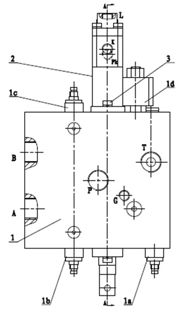
[0013] see figure 1 , The rotary valve of the present invention includes a main valve 1 and a control valve 2, and the two are connected by screws 3. The main valve 1 is equipped with a main relief valve 1a, which acts as overflow protection for the rotary valve. The main valve 1 is also equipped with overload valves 1b and 1c, which play an overload protection and buffer role for the rotary. In addition, it is also equipped with a solenoid valve 1d. After energizing, the slewing is in a free slip state.

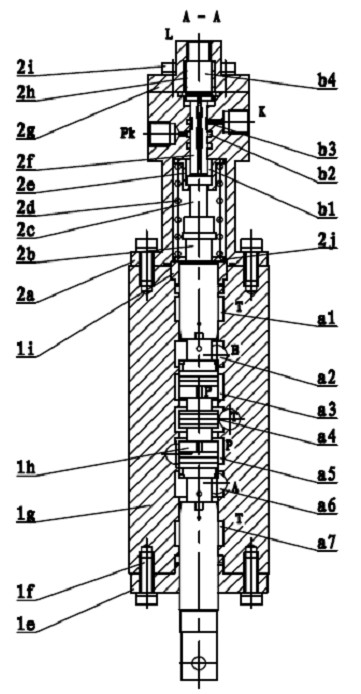
[0014] see figure 2 , the main valve 1 includes a valve body 1g and a main valve stem 1h located in the valve body 1g. The control valve 2 includes a control valve body 2a and a control valve rod 2f' located in the control valve body 2a, and the rotary valve also includes a connecting piece, which includes a connecting screw 2c and a positioning piece 2b. The ...


PUM


Abstract

The invention discloses a rotary valve and a rotary control loop using the same. The rotary valve comprises a master valve and a control valve, wherein the master valve comprises a master valve rod; the control valve comprises a control valve rod; the control valve is connected with a valve body on the master valve; and the master valve rod and the control valve rod push against each other through a connecting piece. The rotary control loop utilizes an oil pump for oil supply; an overflow valve is arranged between the oil pump and the rotary valve; a buffer valve is connected in parallel on an oil line between the master valve of the rotary valve and a motor; a control oil inlet of the control valve of the rotary valve is connected with an external oil source and depends on the external oil source for oil supply; and a control oil outlet is communicated with a brake cylinder to provide oil for the brake cylinder. The invention has the advantages that the oil control of the control cylinder is controlled by the control valve which is connected with the master valve into a whole, namely the movement of the master valve rod can drive the movement of the control valve rod synchronously so that the start of the brake cylinder is controlled well; and the rotary valve and the rotary control loop using the same are not disturbed by the load pressure oscillation, the stable start and stop operation can be realized under big and small flow rate and light and heavy load, and the impact under a dynamic working condition is weakened greatly.

Description

technical field [0001] The invention relates to a rotary valve and a rotary control circuit in a hydraulic component, in particular to a rotary valve for rotary control on a rotary mechanism of a hydraulic truck crane and a rotary control circuit using the rotary valve. Background technique [0002] The slewing mechanism is one of the four major functional mechanisms of the truck crane. Under normal circumstances, the slewing mechanism maintains a braking state under the action of its brake cylinder. To realize the normal slewing function, the brake must be opened first. In actual work, it is required that the rotary start, brake without impact, and the operation should be stable without shaking, especially when starting with a small opening. When the heavy-duty driving suddenly changes from fast to slow, it is required to be stable without abnormal noise. In order to achieve this Purpose, in the slewing hydraulic circuit, relevant hydraulic components must be configured fo...

Claims


Application Information

Patent Timeline
IPC IPC(8): F15B13/02F15B11/02
CPCF15B13/0402B66C23/86
Inventor 刘先爱潘文华杨红
Owner CHANGDE ZHONGLIAN ZHONGKE HYDRAULIC
Why Eureka
Try Eureka