Test bed for circular movement of tricot machine

A motion test, warp knitting machine technology, applied in the testing of mechanical parts, the testing of machine/structural parts, measuring devices, etc. Issues such as lengthening the development time of warp knitting machines

Inactive Publication Date: 2011-04-20
王占洪
View PDF5 Cites 6 Cited by
  • Summary
  • Abstract
  • Description
  • Claims
  • Application Information

AI Technical Summary

Problems solved by technology

In the general design process, computer simulation is often used to check the matching effect, but this is not guaranteed to be foolproof. In many cases, the computer simulation results cannot fully represent the actual operation of the warp knitting machine, so in actual production. It is necessary to constantly modify the warp knitting machine that has been produced to meet the action and coordination requirements, and when modifying, it often leads to the scrapping of the warp knitting machine parts or the whole warp knitting machine. Therefore, not only the length of the warp knitting machine R&D time, and increase the development cost

Method used


Image

  • Test bed for circular movement of tricot machine
  • Test bed for circular movement of tricot machine
  • Test bed for circular movement of tricot machine

Examples


Embodiment Construction

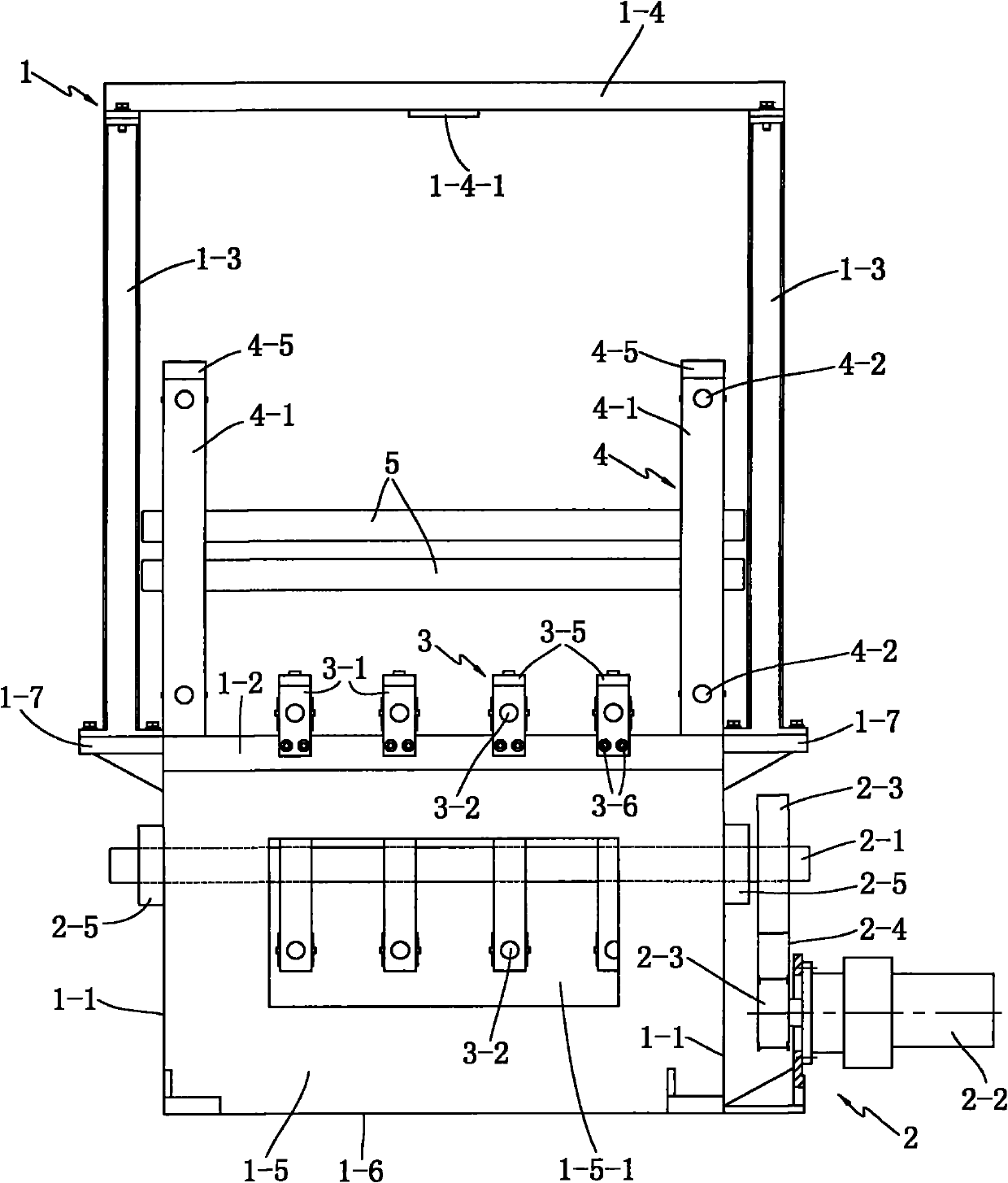
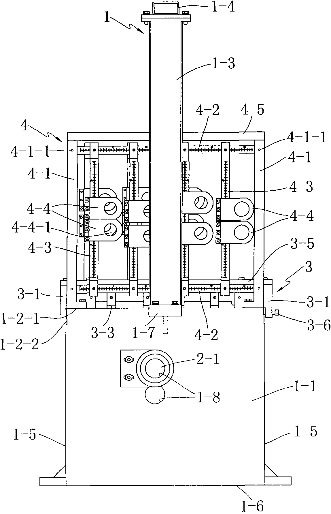
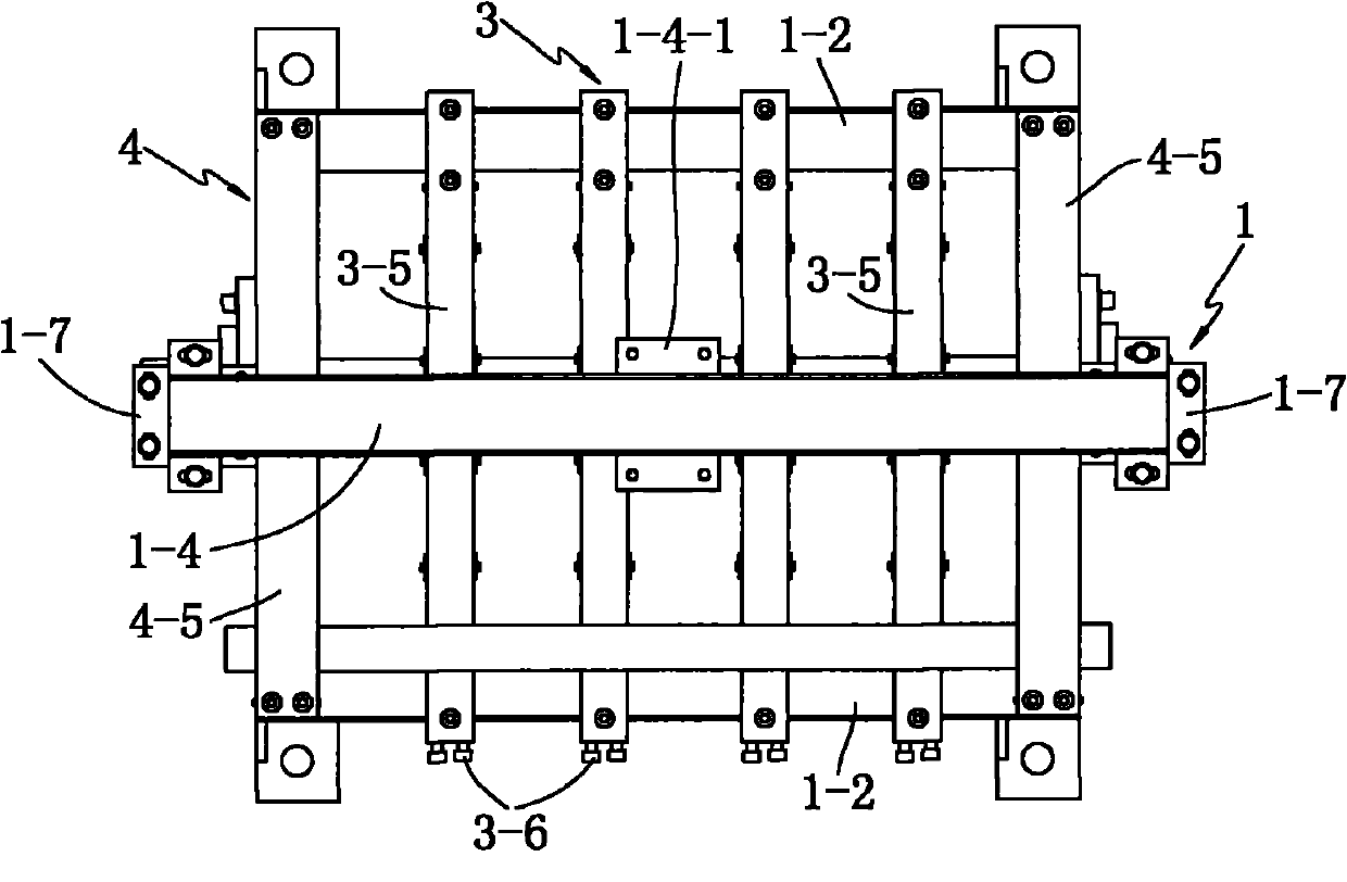
[0022] see Figures 1 to 6 The shown warp knitting machine knitting motion test bench includes: a frame 1, which includes two horizontally parallel wallboards 1-1, and two vertically parallel ones fixedly installed on the wallboard 1 -1 between the first support beam 1-2, the first support 1-3 fixedly connected with the wall panel 1-1, the second support beam 1-4 fixedly connected with the first support 1-3 , the second support beam 1-4 and the first bracket 1-3 form a frame structure, and in the present invention, the first bracket 1-3 is vertically installed on the wall panel 1 through an angle iron 1-7 -1 outside; the transmission device 2, which includes a transmission main shaft 2-1 and a driving device 2-2 that drives the transmission main shaft 2-1 to rotate, and the two ends of the transmission main shaft 2-1 are respectively connected to the transmission main shaft 2-5 through the bearing 2-5. The two wallboards 1-1 are rotationally connected; the link mechanism fixi...


PUM


Abstract

The invention discloses a test bed for circular movement of a tricot machine, which comprises a frame comprising a wall plate, a first support beam, a first bracket and a second support beam; a transmission device, a connecting rod mechanism fixing device and a circulating mechanism fixing device, wherein the transmission device comprises a transmission main shaft and a driving device; the connecting rod mechanism fixing device comprises a connecting rod bracket, a connecting rod bracket shaft, a connecting rod guiderail shaft, a connecting rod pivot fixing base; the connecting rod bracket shaft and the connecting rod guiderail shaft are both marked with scales; the connecting rod bracket is in sliding connection with the first support beam; the number of the connecting rod mechanism fixing devices is more than one and all the connecting rod mechanism fixing devices are arranged between the first support beams; the circulating mechanism fixing device comprises a second bracket, a circulating bracket shaft, a circulating guiderail shaft, and a circulating shaft fixing base; the circulating bracket shaft and the circulating guiderail shaft are both marked with scales; and the number of the circulating mechanism fixing device is two and the two circulating mechanism fixing devices are both fixedly mounted on the upper part of the wall plate. The test bed for circular movement of a tricot machine provided by the invention can directly present the operation and matching of the motion mechanism designed in research stage, so as to modify the design result in time when problems are found, increase the design efficiency and decrease the defective index.

Description

technical field [0001] The invention relates to a test device for the kinematic mechanism of a textile machine, in particular to a test bench for testing the knitting kinematic mechanism of warp knitting machines such as biaxial, multi-axial, and lace machines. Background technique [0002] The knitting motion mechanism of the warp knitting machine generally includes a knitting needle motion mechanism, a needle core motion mechanism, a stripper needle motion mechanism, a sinker motion mechanism and a bar traverse mechanism. For different fabrics, the knitting movement and the mutual cooperation between the various kinematic mechanisms are different. In the process of developing different types of warp knitting machines, it is necessary to continuously modify and correct the design results to meet the mutual cooperation between the various kinematic mechanisms. Require. In the general design process, computer simulation is often used to check the matching effect, but this is...

Claims


Application Information

Patent Timeline
Patent Type & Authority Applications(China)
IPC IPC(8): G01M13/00
Inventor 王占洪赵红霞薛媛朱晓宏姚忆
Owner 王占洪
Why Eureka
Try Eureka