
Optical system for camera

An optical system and camera technology, applied in the field of optical systems, can solve the problems of poor design flexibility of optical systems, difficulties in reducing size and cost of optical systems, increasing length of optical systems, etc., to improve adjacent aberration characteristics , the effect of improving design flexibility

Active Publication Date: 2011-04-20
SAMSUNG ELECTRO MECHANICS CO LTD
View PDF1 Cites 1 Cited by
  • Summary
  • Abstract
  • Description
  • Claims
  • Application Information

AI Technical Summary

Problems solved by technology

[0007] Thus, a plurality of lenses are used in the optical system to maintain high resolution, and it is preferable to configure the optical system by using a glass lens having a high optical transmittance and a high refractive index, however, since the optical system is designed according to the optical system characteristics, so it is difficult for an optical system installed in a mobile communication device to meet the conditions of size reduction and cost reduction
[0008] Therefore, an optical system installed in a mobile communication device uses a plastic lens that is easy to mold, and reduces the number of lenses as much as possible to reduce size and save manufacturing cost, however, the optical system uses a glass lens that has poor performance compared with a glass lens. Plastic lenses of optical performance, it is difficult to satisfy the optical performance by designing the optical system, and the design flexibility of the optical system is deteriorated due to the reduction in the number of lenses
[0009] Meanwhile, as a general design of an optical system, a design method is adopted in which an aperture stop is positioned at the forefront of each of a plurality of lenses, and the plurality of lenses are arranged in sequence, but, in this case, passing through the aperture The light at the end of the diaphragm causes many aberrations (aberration)
[0010] In addition, when the aperture stop located at the frontmost part of the optical system is far away from the first lens close to the object, the size of the first lens increases and the length of the optical system increases, thereby significantly deteriorating the optical performance

Method used


Image

  • Optical system for camera
  • Optical system for camera
  • Optical system for camera

Examples


no. 1 approach

[0087] Table 1 shown below shows examples of values ​​according to the first embodiment of the present invention.

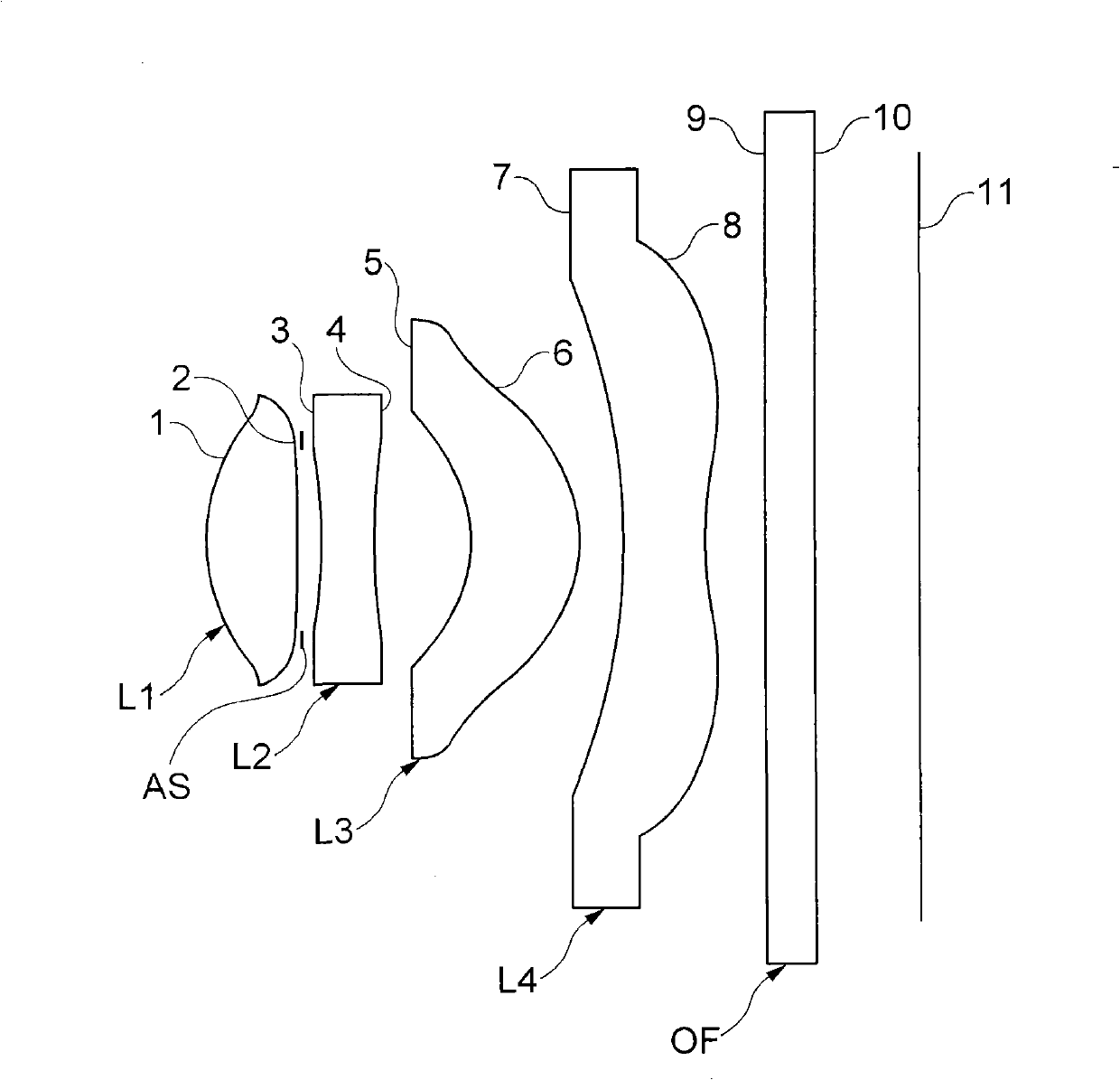
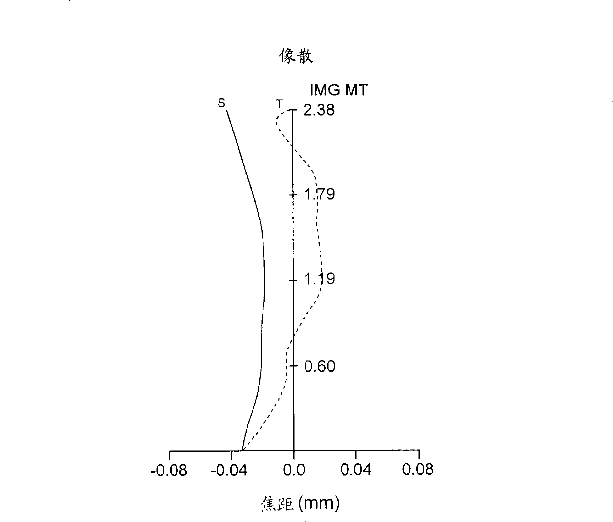
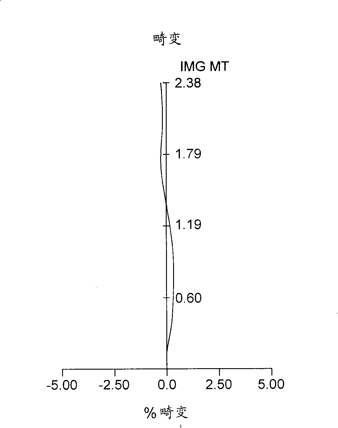
[0088] also, figure 1 is a configuration diagram showing the configuration of a lens of an optical system for a camera according to the first embodiment of the present invention, Figure 2A and Figure 2B are shown in Table 1 and figure 1 astigmatism and distortion aberrations of the optical system shown, and image 3 A to image 3 D is a diagram of coma aberration per field according to the first embodiment. In addition, in Figure 2A In the astigmatism diagram, "S" indicates radial and "T" indicates tangential.

[0089] In the first embodiment, the viewing angle is 64 degrees, the distance TL from the object-side surface 1 of the first lens L1 to the top surface is 4.2 mm, and the effective focal length f of the entire optical system is 3.6 mm. In addition, each of the first lens L1 to the fourth lens L4 is configured of a plastic lens.

[0090] 【Table ...

no. 2 approach

[0097] Table 3 shown below shows examples of values ​​according to the second embodiment of the present invention.

[0098] also, Figure 4 is a configuration diagram showing the configuration of a lens of an optical system for a camera according to a second embodiment of the present invention, Figure 5A and Figure 5B are shown in Table 3 and Figure 4 astigmatism and distortion aberrations of the optical system shown, while Image 6 A to Image 6 D is a diagram of coma aberration per field according to the second embodiment. In addition, in Figure 5A In the astigmatism diagram, "S" indicates radial and "T" indicates tangential.

[0099] In the second embodiment, the viewing angle is 50 degrees, the distance TL from the object-side surface 1 of the first lens L1 to the top surface is 5.5 mm, and the effective focal length of the entire optical system is 5.5 mm. In addition, each of the first lens L1 to the fourth lens L4 is configured of a plastic lens.

[0100] 【ta...

no. 3 approach

[0107] Table 5 shown below shows examples of values ​​according to the third embodiment of the present invention.

[0108] also, Figure 7 is a configuration diagram showing the configuration of a lens of an optical system for a camera according to a third embodiment of the present invention, Figure 8A and Figure 8B are shown in Table 5 and Figure 7 astigmatism and distortion aberrations of the optical system shown, while Figure 9 A to Figure 9 D is a diagram of coma aberration per field according to the third embodiment. In addition, in Figure 8A In the astigmatism diagram, "S" indicates radial and "T" indicates tangential.

[0109] In the third embodiment, the viewing angle is 60 degrees, the distance TL from the object-side surface 1 of the first lens L1 to the top surface is 3.8 mm, and the effective focal length of the entire optical system is 3.8 mm. In addition, each of the first lens L1 to the fourth lens L4 is configured of a plastic lens.

[0110] 【tabl...


PUM


Abstract

The present invention relates to an optical system for a camera. The optical system for a camera in accordance with the present invention includes: a first lens that has a positive refractive index and has a convex shape toward an object; a second lens that has a negative refractive index and has a concave shape at both surfaces; a third lens that has the positive refractive index and has the convex shape upwards; and a fourth lens that has the negative refractive index and has a concave surface on an object-side surface, and has at least one inflection point on an image surface. It is possible to implement a compact optical system for a camera which can be applied to a mobile communication terminal by improving design flexibility.

Description

[0001] CROSS-REFERENCE TO RELATED APPLICATIONS [0002] This application claims the benefit of Korean Patent Application No. 10-2009-0089592, filed with the Korean Intellectual Property Office on September 22, 2009, the disclosure of which is incorporated herein by reference. technical field [0003] The present invention relates to an optical system for a camera, and more particularly, to an optical system for a camera in which an aperture stop is provided between lenses, and all the lenses constituting the optical system are composed of non- Spherical plastic lens composition. Background technique [0004] In recent years, with the increasing number of mobile communication devices such as mobile communication terminals, PDAs, and smartphones, services provided through communication technologies have become diverse, providing various types of additional functions in addition to basic communication functions . [0005] Among these functions, camera modules are mainly insta...

Claims


Application Information

Patent Timeline
Patent Type & Authority Applications(China)
IPC IPC(8): G02B13/00G02B7/00G02B13/18
CPCG02B13/004G02B9/34G02B13/18
Inventor 赵镛主
Owner SAMSUNG ELECTRO MECHANICS CO LTD
Features
  • Generate Ideas
  • Intellectual Property
  • Life Sciences
  • Materials
  • Tech Scout
  • Unparalleled Data Quality
  • Higher Quality Content
  • 60% Fewer Hallucinations
Learn More