Check patentability & draft patents in minutes with Patsnap Eureka AI!

Radio frequency identification (RFID) tag chip and RFID tag

A technology of RFID tags and chips, which is applied in the field of RFID applications, can solve the problems of not setting up radio frequency power detection sensors and being unable to expand the use of mobile communication industries, and achieve the effect of improving anti-interference ability

Inactive Publication Date: 2011-04-20
珠海银邮光电技术发展股份有限公司
View PDF2 Cites 3 Cited by
  • Summary
  • Abstract
  • Description
  • Claims
  • Application Information

AI Technical Summary

Problems solved by technology

[0005] The purpose of the present invention is to provide an RFID tag chip and an RFID tag, aiming to solve the problem that the existing RFID tags cannot be extended to the mobile communication industry because there is no radio frequency power detection sensor inside.

Method used


Image

  • Radio frequency identification (RFID) tag chip and RFID tag
  • Radio frequency identification (RFID) tag chip and RFID tag
  • Radio frequency identification (RFID) tag chip and RFID tag

Examples


Embodiment Construction

[0018] In order to make the object, technical solution and advantages of the present invention more clear and definite, the present invention will be further described in detail below with reference to the accompanying drawings and examples.

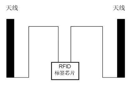
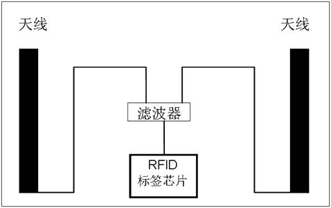
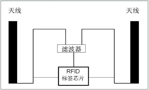
[0019] Such as figure 2 As shown, an RFID tag provided by Embodiment 1 of the present invention includes an RFID tag chip and an antenna. According to the principle analysis of the existing passive RFID tag, in order to improve its anti-interference ability, a filter is set before the dual dipole antenna is introduced into the RFID tag chip. The antenna is connected to the filter, and the filter is connected to the RFID tag chip.

[0020] Wherein, the bandwidth of the filter is correspondingly adjusted according to the frequency of the original distribution system. If the distribution system is a GSM network, the bandwidth is set at 840~842MHz; if the distribution system is a CDMA network, the bandwidth is set at 920~922MHz. The out-...


PUM


Abstract

The invention discloses a radio frequency identification (RFID) tag chip and an RFID tag, wherein the RFID tag comprises an antenna, a filter and the RFID tag chip with a radio frequency detection module; the antenna is connected with the filter; the filter is connected with the RFID tag chip; and the radio frequency detection module in the RFID tag chip is directly connected with the antenna. The RFID tag chip is used to improve antijamming capability of the RFID tag chip, and is applied to mobile communication industry with a large area, in particular to effect detection of areas covered by mobile signals, fixed asset inventory and the like.

Description

technical field [0001] The invention relates to an RFID application field, in particular to an RFID tag chip and an RFID tag. Background technique [0002] The internal principles of passive RFID tags currently on the market are as follows: figure 1 shown. The passive RFID tag includes an RFID tag chip and a tag antenna or coil, which uses the principle of inductive coupling or electromagnetic backscatter coupling to realize communication with the reader. The RFID tag chip is mainly composed of three parts: an analog radio frequency unit, a data control unit and an EEPROM storage unit. The analog radio frequency unit mainly realizes functions such as power generation, modulation / demodulation, clock generation, and power-on reset, and provides stable voltage for the IC. The obtained data is demodulated and provided to the data control unit for processing, and at the same time, the data processed by the data control unit is returned to the reader after being modulated. The ...

Claims


Application Information

Patent Timeline
IPC IPC(8): G06K19/077
Inventor 方道奎
Owner 珠海银邮光电技术发展股份有限公司
Features
  • R&D
  • Intellectual Property
  • Life Sciences
  • Materials
  • Tech Scout
  • Unparalleled Data Quality
  • Higher Quality Content
  • 60% Fewer Hallucinations
Learn More