Control method for realizing switching of old and new display interfaces

A display interface and control method technology, which is applied in image data processing, instruments, image data processing, etc., can solve problems such as obstacles and high costs, and achieve the effects of reducing energy consumption, reducing code volume, and improving code execution efficiency and reliability

Inactive Publication Date: 2012-07-18
NINGBO SUNRUN ELEC & INFO ST&D
View PDF4 Cites 0 Cited by
  • Summary
  • Abstract
  • Description
  • Claims
  • Application Information

AI Technical Summary

Problems solved by technology

However, the existing three-dimensional switching mode of the display interface is generally based on a complex control method for switching between the old and new display interfaces. In this way, while the existing three-dimensional switching mode of the display interface brings gorgeous visual experience to the user, Hardware such as high-speed processors and high-capacity memory are needed as its underlying support, such as smart phones, personal computers, etc. Therefore, the cost of equipment with a three-dimensional switching method of the display interface is relatively high, and the high cost hinders the three-dimensional switching of the display interface. The application of the method on low-end hardware platforms with low hardware support capabilities (processors with low computing power and low-capacity memory, etc.), in order to enable low-end users to also have a three-dimensional switching method of the display interface A simple and feasible control method for switching between old and new display interfaces is essential
At present, in the prior art, there is no control method applicable to the low-end and middle-end hardware platforms for switching between old and new display interfaces.

Method used


Image

  • Control method for realizing switching of old and new display interfaces
  • Control method for realizing switching of old and new display interfaces
  • Control method for realizing switching of old and new display interfaces

Examples


Embodiment Construction

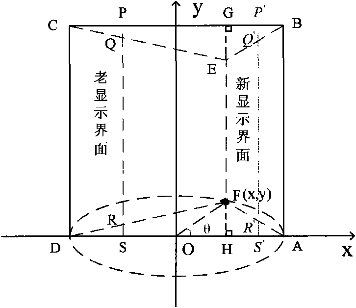
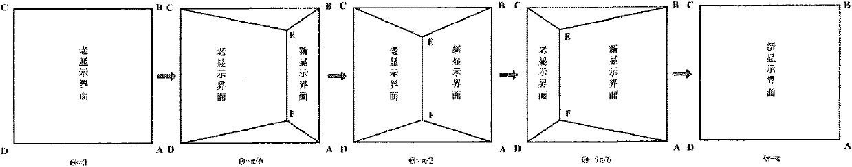
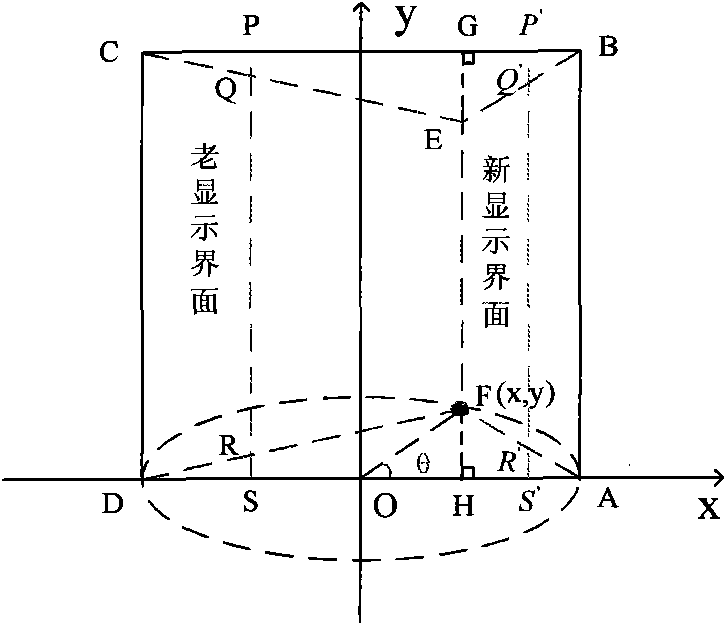
[0013] The present invention will be further described below in conjunction with accompanying drawing.

[0014] The present invention is used to realize the control method for switching between old and new display interfaces, taking the lower edge AD of the effective display area ABCD of the display screen as the X axis, and the vertical line passing through the midpoint of the lower edge AD and intersecting with the upper edge BC of the effective display area ABCD as the Y axis Establish a Cartesian coordinate system in which the expression x = ± ab b 2 + a 2 tan 2 ...


PUM


Abstract

The invention discloses a control method for realizing the switching of old and new display interfaces, which is suitable for middle-end and low-end hardware platforms. The control method comprises the following steps of: determining horizontal and vertical coordinates of a first demarcation point (F) through an equation set in the specification, wherein theta is more than or equal to 0 and less than or equal to Pi and is not equal to half of Pi, x is a positive value when theta is more than or equal to 0 and less than half of Pi, x is a negative value when theta is more than half of Pi and less than or equal to Pi, x is equal to 0 and y is equal to b when theta is equal to half of Pi, a is L1 / 2, b is one value of an interval (0, L2), and L1 and L2 are respectively the pixel numbers of aneffective display area (ABCD) of a display screen in a width direction and a height direction; defining the horizontal and vertical coordinates of a second demarcation point (E) as (x, y'), wherein xis the horizontal coordinate of the first demarcation point (F), and the vertical coordinate y' of the second demarcation point (E) is one value of an interval (y, L2); displaying the new display interface in a first quadrangle (BAFE) and the old display interface in a second quadrangle (CDFE) by utilizing an image compression method; selecting a value for theta from 0 to pi, wherein each theta determines a display state, and the display states are sequentially displayed in the effective display area (ABCD) of the display screen to realize the three-dimensional switching of the old and new display interfaces.

Description

technical field [0001] The invention relates to the technical field of display interface switching control, in particular to a control method for realizing switching between old and new display interfaces. Background technique [0002] The rich and varied three-dimensional switching methods of the display interface overcome the rigid effect brought to the user by the traditional two-dimensional switching method, and make the switching process of the display interface more natural and friendly, thereby achieving a satisfactory visual effect. The three-dimensional display interface The switching mode refers to replacing the old display interface with a new display interface in a three-dimensional dynamic change mode (such as inversion, valgus, twisting, etc.). However, the existing three-dimensional switching mode of the display interface is generally based on a complex control method for switching between the old and new display interfaces. In this way, while the existing thr...

Claims


Application Information

Patent Timeline
Patent Type & Authority Patents(China)
IPC IPC(8): G06T1/00
Inventor 何加铭李艳王吉文贾德祥高宇栋史爱军樊玲慧史智慧陈恳杨逊豪
Owner NINGBO SUNRUN ELEC & INFO ST&D
Why Eureka
Try Eureka