
Staggered pulse wave width modulation control power module system and operating method thereof

A technology of pulse width modulation and modular system, which is applied in the direction of converting irreversible AC power input into DC power output, etc. It can solve the problems of increasing the use of components for EMI filters and the difficulty of expanding EMI filters.

Inactive Publication Date: 2013-08-21
DELTA ELECTRONICS INC
View PDF4 Cites 0 Cited by
  • Summary
  • Abstract
  • Description
  • Claims
  • Application Information

AI Technical Summary

Problems solved by technology

Therefore, in addition to increasing the components used in the EMI filter, it will also cause difficulties in the expansion of these EMI filters.
In addition, if one of the two interleaved boost circuits fails, the synchronous control and current sharing functions cannot be normally provided by the PWM controller.

Method used


Image

  • Staggered pulse wave width modulation control power module system and operating method thereof
  • Staggered pulse wave width modulation control power module system and operating method thereof
  • Staggered pulse wave width modulation control power module system and operating method thereof

Examples


Embodiment Construction

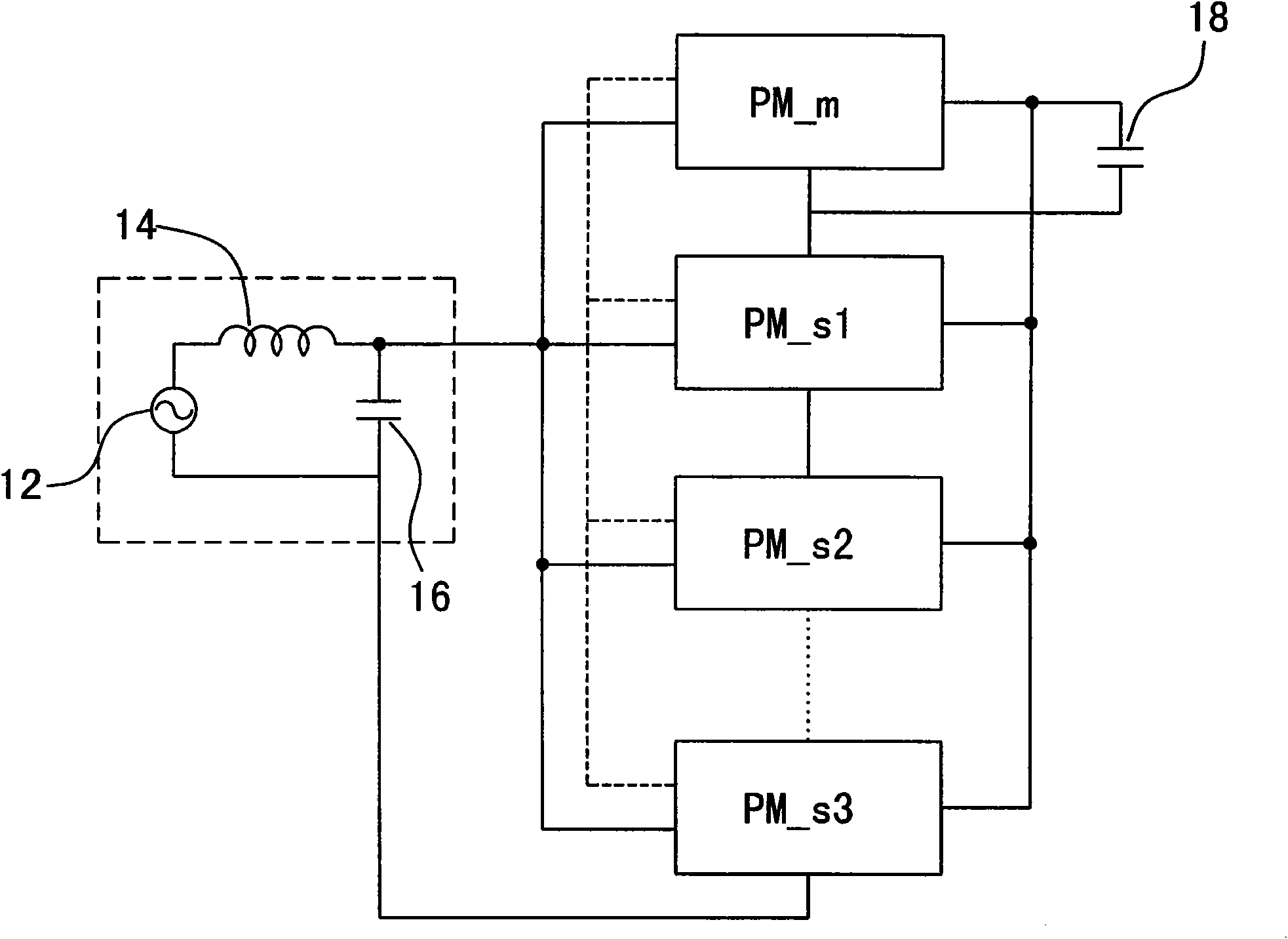
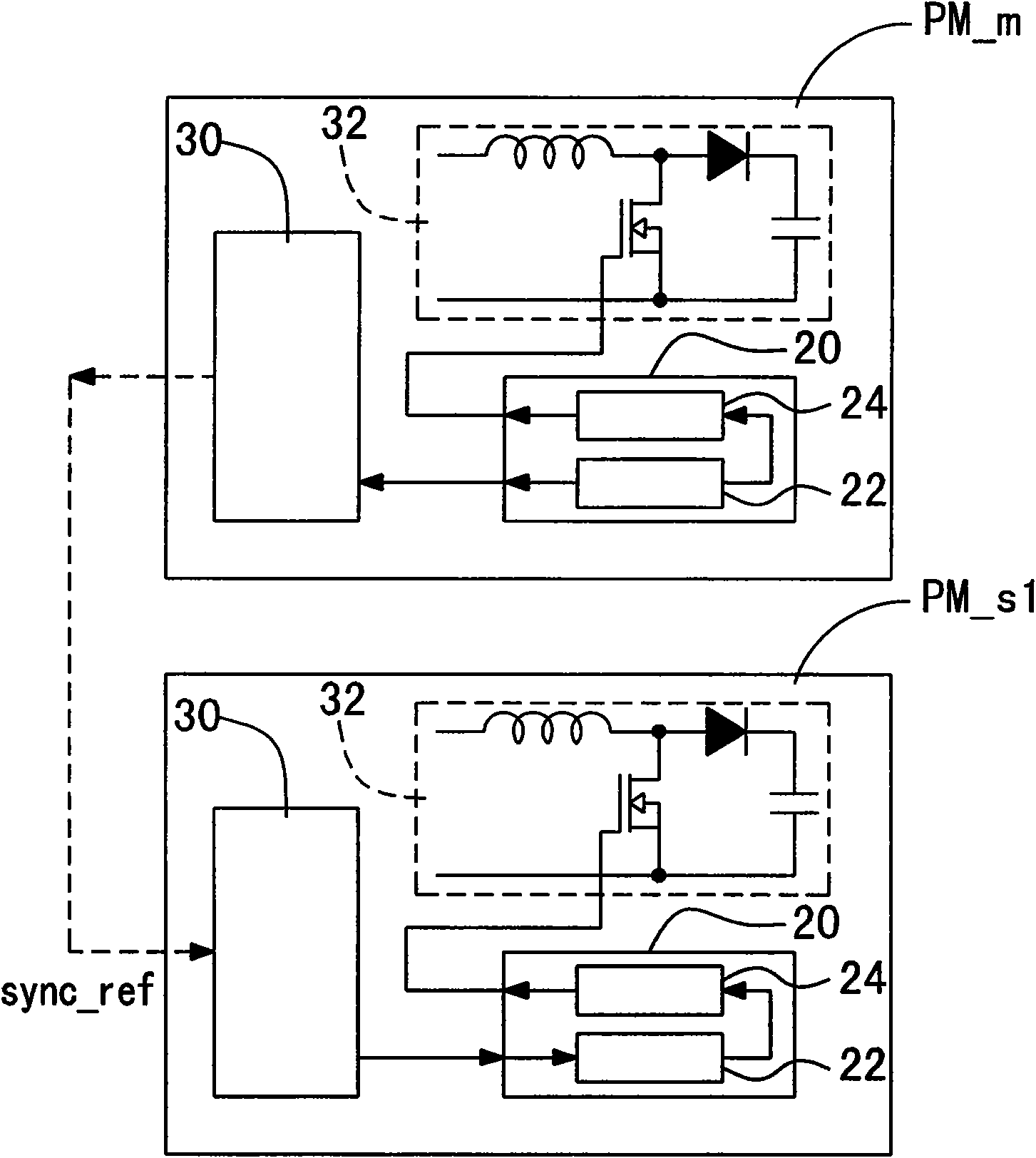
[0039] Figure 1A Shown is a power module system according to a preferred embodiment of the present invention, wherein an AC power source 12 is supplied to a plurality of power modules through an EMI filter (including an inductor 14 and a capacitor 16 ). The power modules include a master power module (master power module) PM_m and at least one slave power module (slave power module) PM_si, i=1, 2 . . . . Moreover, each of the power modules has an identification number PM_id, which is used as the basis for calculating the phase offset. The PWM control signals of the slave power modules PM_s are controlled by the master power module PM_m and interleaved with each other, and the output voltages of the power modules are supplied to an output terminal 18 .

[0040] Since each power module has similar hardware, the hardware of the single slave power module PM_s1 is described first. See Figure 1B, illustrating the internal schematic diagram of the power module of the present inv...


PUM


Abstract

The invention relates to a staggered pulse wave width modulation control power module system and an operating method thereof. The power module system comprises at least two power modules, and each power module has a specific identification number. Firstly, the power module with set identification number extreme value is set as a primary power module, and remaining power modules are set as secondary power modules. The primary power module transmits a synchronous reference signal to the secondary power modules, and each secondary power module executes the phase lock operation of a phase offset, wherein each secondary power module has different phase offsets. The phase lock operation makes each secondary power module output a frequency switching signal, wherein the frequency switching signal is synchronous with the addition result of synchronous reference signal and the phase offset. The digital signal processor of each power module outputs the frequency switching signal so as to control a corresponding pulse wave width modulation control signal.

Description

technical field [0001] The invention relates to a power module controlled by pulse width modulation and an operation method thereof, in particular to a power module system and a control method thereof using a phase-locked loop to achieve interleaved pulse width modulation control. Background technique [0002] Due to the gradual development of electronic products in the direction of high power, high transmission rate, and miniaturization, the distribution density of circuit components increases and the volume of circuits is greatly reduced. Therefore, as circuits become more compact, more components are laid out in tight spaces, increasing the chance of interference. Among them, Electromagnetic interference (EMI) is the most troublesome, and has long been a blind spot in the design of electronic equipment and systems. [0003] The suppression objects of electromagnetic interference are mainly divided into radiated electromagnetic interference (Radiated EMI) and conducted el...

Claims


Application Information

Patent Timeline
Patent Type & Authority Patents(China)
IPC IPC(8): H02M7/21
Inventor 王学政张瑛淞
Owner DELTA ELECTRONICS INC
Learn More