Transmission method for uplink control signaling, base station and user equipment
A technology for user equipment and control signaling, applied in wireless communication, electrical components, etc., can solve the problems of failing to meet the feedback requirements of LTE-Advanced and rough granularity of resource division
- Summary
- Abstract
- Description
- Claims
- Application Information
AI Technical Summary
Problems solved by technology
Method used
Image

Examples
Embodiment 1
[0046] Embodiment 1: OVSF code time-frequency two-dimensional code division multiplexing
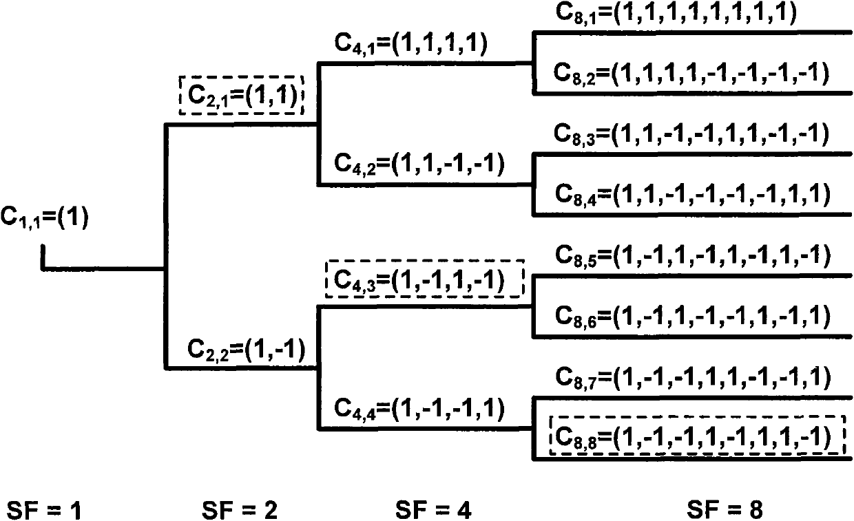
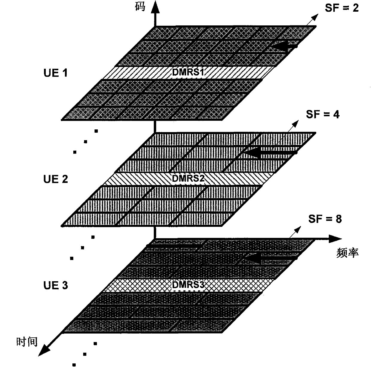
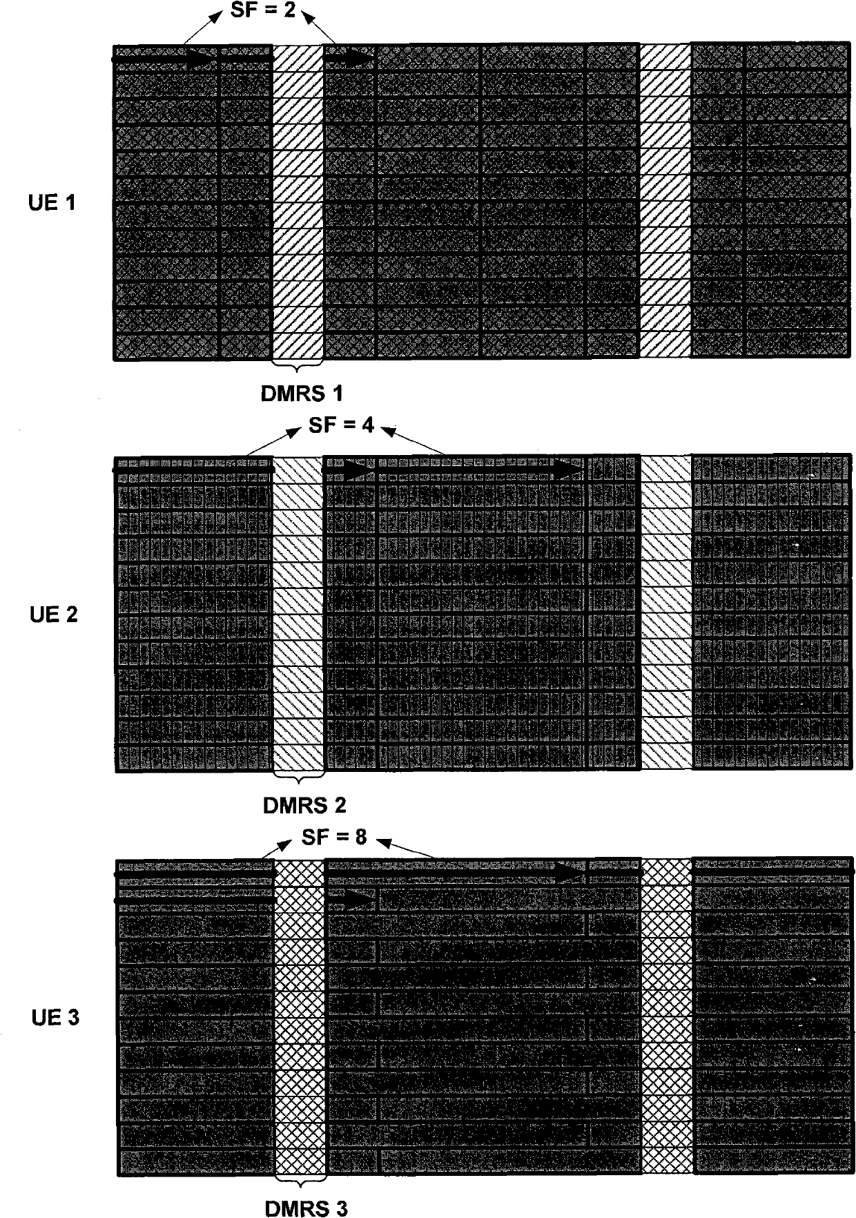
[0047] If the uplink control channel resource occupied by the user equipment occupies the entire resource block of the uplink control channel, the uplink control channel does not need to be multiplexed among different user equipments, but only allocated to the user equipment for use, the base station The feedback resources are notified to the user equipment through dynamic designation or high-level signaling notification, where the sequence in the feedback resource is the OVSF code with SF of 1; if the user equipment only needs to occupy part of the uplink control channel resources, the base station will select Appropriate number of user equipments multiplex the same uplink control channel, and different users adopt the same or different sequences according to the demand of control signaling feedback amount, here is the same or different SF OVSF codes, and the base station dynamically s...
Embodiment 2
[0055] Embodiment 2: Joint OVSF code time-frequency two-dimensional code division multiplexing and time division multiplexing
[0056] Figure 5The second scheme of the uplink control channel sub-channelization method is given: joint OVSF code time-frequency two-dimensional code division multiplexing and time division multiplexing. Different from the first embodiment, the sub-channel division method in the second embodiment is performed in the manner of joint time division and time-frequency two-dimensional code division. Firstly, the physical resource of the uplink control channel is preferably divided into several resource sub-blocks of 4 SC-FDMA symbols, and then the control signaling of different user equipments in each resource sub-block is performed in accordance with the method in Embodiment 1. OVSF Code time-frequency two-dimensional code division multiplexing, and the physical resource mapping method after the signaling symbol is spread is the same as that in the f...
Embodiment 3
[0062] Embodiment 3: Joint OVSF code block spreading code division multiplexing and time division multiplexing
[0063] Image 6 The third scheme of the uplink control channel sub-channelization method is given: joint OVSF code block spreading code division multiplexing and time division multiplexing. Different from Embodiment 2, OVSF code time-frequency two-dimensional spread spectrum is no longer performed in each resource sub-block, but time-one-dimensional block spread spectrum is performed between SC-FDMA symbols in the resource sub-block, preferably The spread spectrum code is the OVSF code, and the supported SFs are 1, 2, and 4.
[0064] Image 6 In one resource sub-block of the uplink control channel physical resources, the SC-FDMA symbols composed of the control signaling symbols of user equipment 1 are mapped to two SC-FDMA symbols after being spread by the OVSF code block with SF of 2, The rest of the control signaling symbols are similarly spread and mapped to...
PUM
 Abstract
Description
Claims
Application Information
 - R&D
- Intellectual Property
- Life Sciences
- Materials
- Tech Scout
- Unparalleled Data Quality
- Higher Quality Content
- 60% Fewer Hallucinations
Browse by: Latest US Patents, China's latest patents, Technical Efficacy Thesaurus, Application Domain, Technology Topic, Popular Technical Reports.
© 2025 PatSnap. All rights reserved.Legal|Privacy policy|Modern Slavery Act Transparency Statement|Sitemap|About US| Contact US: help@patsnap.com