Ultrasonic probe, method for manufacturing the same and ultrasonic diagnostic device

A manufacturing method and ultrasonic technology, applied in the directions of ultrasonic/sonic/infrasonic diagnosis, sonic diagnosis, infrasonic diagnosis, etc., can solve the problems of incomplete function of cMUT chip, incomplete function of ultrasonic transmission and reception, etc., to prevent functional failure. full effect

Inactive Publication Date: 2011-04-20
HITACHI MEDICAL CORP
View PDF1 Cites 13 Cited by
  • Summary
  • Abstract
  • Description
  • Claims
  • Application Information

AI Technical Summary

Problems solved by technology

For cMUT chips, the transmission and reception of ultrasonic waves caused by the internal space divided by the hardened frame and membrane become incomplete
Prevention of incomplete functionality of cMUT chips due to percolation based on this binder remains unresolved

Method used


Image

  • Ultrasonic probe, method for manufacturing the same and ultrasonic diagnostic device
  • Ultrasonic probe, method for manufacturing the same and ultrasonic diagnostic device
  • Ultrasonic probe, method for manufacturing the same and ultrasonic diagnostic device

Examples


no. 1 approach

[0077] Below, refer to Figure 5 and Figure 6 , to describe the first embodiment.

[0078] (3-1. Components of the ultrasonic probe 2)

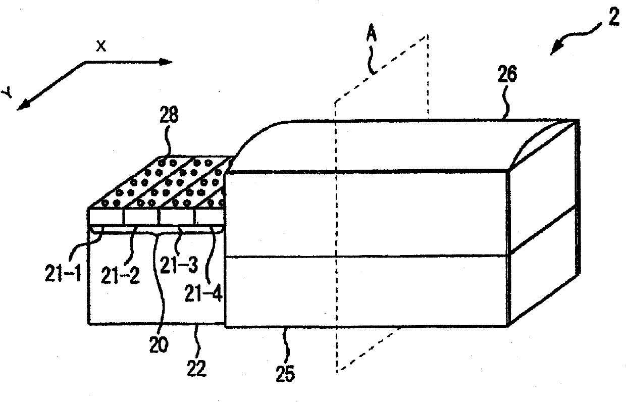
[0079] Figure 5 It is a schematic diagram showing the ultrasonic probe 2 of the first embodiment. Figure 5 yes figure 2 Plane A sectional view of the ultrasonic probe 2.

[0080] A conductive film 76 is formed along the ultrasonic radiation surface of the cMUT chip 20 , the side surfaces of the flexible substrate 72 and the support layer 22 , and an insulating film 78 as an insulating layer is formed on the inner surface of the acoustic lens 26 . The conductive film 76 and the insulating film 78 are formed by, for example, vacuum evaporation, sputtering, or CVD. The conductive film 76 is a Cu or Al film or the like, and has electrical conductivity. The insulating film 78 is bonded to the conductive film 76 by an adhesive. The insulating film 78 is, for example, a silicon oxide film, a paraxylene film, or the like, and has chemical ...

no. 5 approach

[0141] Below, refer to Figure 11 and Figure 12 , and the fifth embodiment will be described. The fifth embodiment relates to electrical connection between the cMUT chip 20 and the flexible substrate 72 .

[0142] Figure 11 It is a schematic diagram showing the ultrasonic probe 2f of the fifth embodiment. Figure 11 and figure 2 The plane A sectional view of is comparable.

[0143] Figure 12 yes Figure 11 A detailed view of the electrical connections.

[0144] In the first embodiment, it was described that the flexible substrate 72 and the cMUT chip 20 are electrically connected via the wire 86 according to the wire bonding method, but in the fifth embodiment, the flexible substrate 72 and the cMUT chip are connected via the through hole 161 or the through hole 171 The cMUT chip 20 is electrically connected.

[0145] The signal pattern of the flexible substrate 72 is electrically connected to the electrodes of the cMUT chip 20 on the rear surface of the periphera...


PUM


Abstract

The present invention relates to a ultrasonic probe, a method for manufacturing the same and a ultrasonic diagnostic device. The ultrasonic probe is provided with a cMUT chip having a plurality of vibration elements that change electro-mechanical coupling coefficients or sensitivities in accordance with a bias voltage to transmit and receive ultrasonic waves, an electrically conductive layer formed on the ultrasonic irradiation side of the cMUT chip, an acoustic lens arranged on the ultrasonic irradiation side of the cMUT chip, an insulation layer formed in the direction opposite to the ultrasonic irradiation side of the cMUT chip, a housing unit that stores the acoustic lens in which the electrically conductive layer and the insulation layer are fixed with an adhesive and the acoustic lens, wherein the insulation layer is formed by a material that includes at least either silicon oxide or paraxylylene to prevent a solvent of the adhesive from soaking into the adhered portion.

Description

technical field [0001] The present invention relates to an ultrasonic probe for taking diagnostic images, a manufacturing method thereof, and an ultrasonic diagnostic device. Background technique [0002] An ultrasonic diagnostic apparatus is an apparatus that captures diagnostic images based on reflected echo signals output from an ultrasonic probe. A plurality of ultrasonic vibrators are arranged on the ultrasonic probe. The ultrasonic vibrator converts the drive signal into ultrasonic waves, transmits the ultrasonic waves to the subject, and receives reflected echo signals generated from the subject, and converts them into electrical signals. [0003] In recent years, ultrasonic probes using cMUT (Capacitive Micromachined Ultrasonic Transducer) have been developed. cMUT is an ultra-fine capacitive ultrasonic vibrator manufactured by semiconductor microfabrication technology. In the cMUT, the sensitivity of ultrasonic reception and transmission, that is, the electromech...

Claims


Application Information

Patent Timeline
Patent Type & Authority Applications(China)
IPC IPC(8): A61B8/00H04R19/00H04R31/00
CPCA61B8/13A61B8/4455B06B1/0292A61B8/06G01N29/2406Y10T29/49005
Inventor 佐野秀造吉村保广永田达也深田慎佐光晓史
Owner HITACHI MEDICAL CORP
Why Eureka
Try Eureka