Dry vacuum pump

A technology for dry vacuum pumps and exhaust chambers, applied in the direction of rotary piston pumps, pumps, pump components, etc., can solve the problems of reduced exhaust capacity and increased costs, and achieve cost reduction, easy use and maintenance, and prevent malfunctions full effect

Active Publication Date: 2014-12-31
ULVAC INC
View PDF9 Cites 0 Cited by
  • Summary
  • Abstract
  • Description
  • Claims
  • Application Information

AI Technical Summary

Problems solved by technology

[0013] In addition, in the vacuum pump such as Patent Document 3, in order to prevent the inflow of reactive gases from the exhaust chamber to the gear box, an inert gas flow path is provided in the non-contact shaft seal mechanism, but there is a large amount of inert gas that will lead to cost. Improvement and decrease in exhaust capacity

Method used


Image

  • Dry vacuum pump
  • Dry vacuum pump
  • Dry vacuum pump

Examples


no. 1 approach

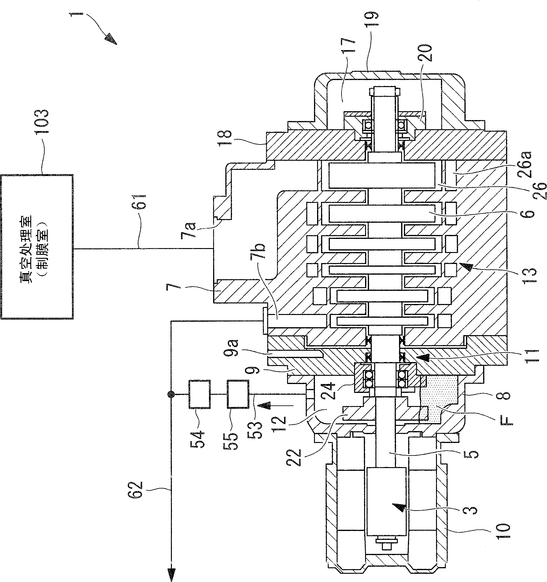
[0063] figure 1 An overview of a vacuum processing system using the dry vacuum pump 1 according to the first embodiment of the present invention is shown.

[0064] A plasma CVD apparatus (vacuum processing apparatus) 101 has a film deposition chamber 103 , and a dry vacuum pump 1 is provided as a system for evacuating the interior of the film deposition chamber 103 . The pair of film-making chambers 103 exceeds 1m 2 film formation on a large-area glass substrate (not shown). The film forming chamber 103 and silane gas (SiH 4 ) and hydrogen (H 2 ) and purge gas (NF 3 ) are connected to the gas supply channels 104, 105, and 106 that are supplied to the film forming chamber 103, respectively. In addition, an exhaust system 61 for exhausting gas is provided in the film forming chamber 103 .

[0065] The exhaust system 61 has an exhaust flow path 110 provided with a turbomolecular pump (TMP) 109 for high vacuum, and a flow path 112 provided with a flow control valve (CV) 111 ...

no. 2 approach

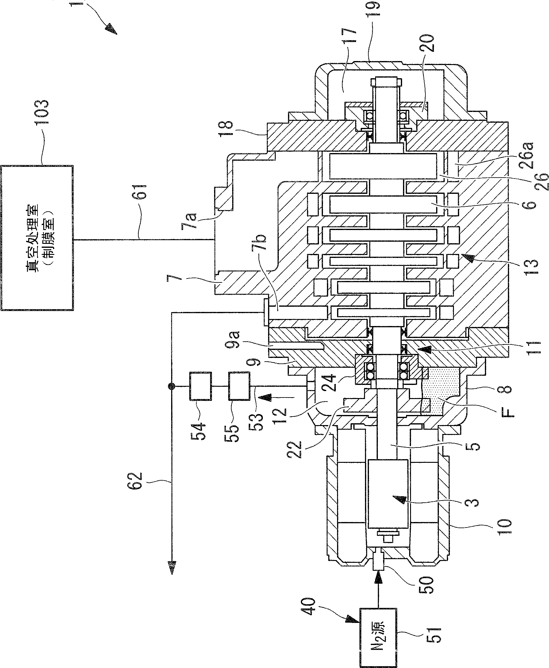
[0143] In the second embodiment, a purge mechanism (purge device) 40 is provided in the dry vacuum pump 1 of the first embodiment, and descriptions of parts that overlap with those of the first embodiment are omitted.

[0144] The purification mechanism (purification device) 40 will be described below.

[0145] Such as Figure 9 and Figure 10 As shown, the purification mechanism 40 has: a gas introduction part 50 and a gas discharge passage 53 . The purification mechanism 40 is a mechanism for diluting hydrogen in the gas to be exhausted that leaks into the lubricating chamber 12 through the sealing mechanisms 11 and 16 with an inert gas, and uses an inert gas that does not react with gas components of the gas to be exhausted. As an inert gas, nitrogen gas, argon gas, etc. are inexpensive, and even if they are mixed into the exhaust chamber 13, since the molecular weight is large, the decrease in the exhaust capacity of the dry vacuum pump is less likely to be suppressed, s...

no. 3 approach

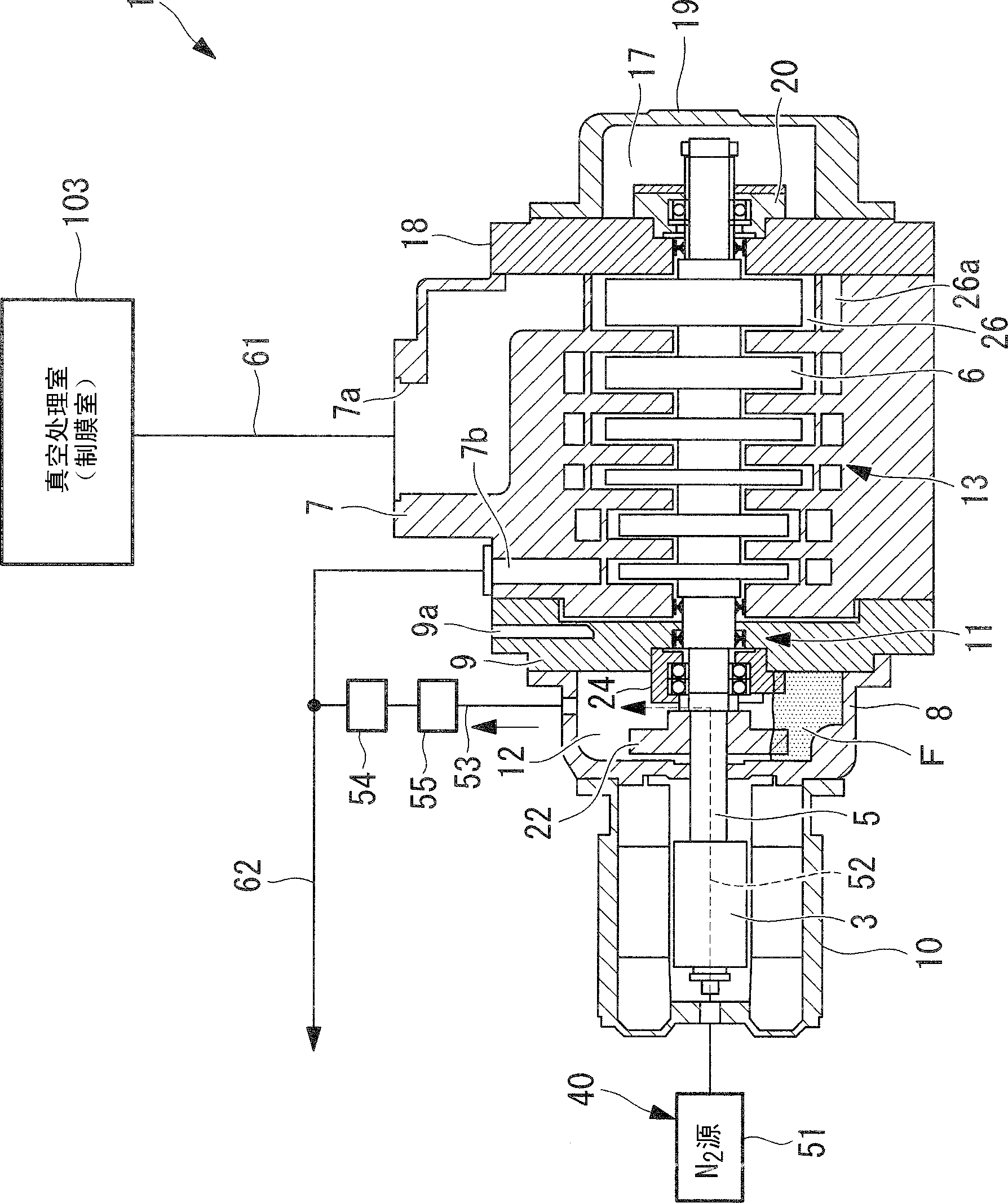
[0159] The third embodiment is a form in which the gas introduction passage 52 is provided in the gas introduction part 50 of the second embodiment, and the description of the parts overlapping with the second embodiment will be omitted.

[0160] Such as Figure 11 As shown, the purification mechanism (purification device) 40 has a gas introduction passage 52 and a gas discharge passage 53 . The purification mechanism 40 is used to dilute the hydrogen in the gas to be exhausted that leaks into the lubrication chamber 12 through the sealing mechanisms 11 and 16 with an inert gas. The case where nitrogen gas is used as the inert gas will be described.

[0161] The gas introduction passage 52 is formed on the rotating shaft (rotator) of the electromagnetic motor 3 and the axial center of the shaft 5 . One end of the gas introduction passage 52 is connected to the nitrogen introduction source 51 provided outside the electromagnetic motor 3 via the gas introduction part 50 formed ...


PUM


Abstract

Between an exhaust chamber (13) and a lubrication chamber (12), a second seal (28) that seals between a cylinder (7) that partitions the exhaust chamber(13) and a first shaft (5) and a first seal (27) that seals between a side cover (9) that partitions the lubrication chamber (12) and the first shaft (5) are provided. A gas introduction space (29) to which a seal gas is supplied is provided between the second seal (28) and the first seal (27). The second seal (28) and the first seal (27) each have a base part and a pair of ring-like lips (31, 32, 33, and 34) extending from the base part toward the first shaft (5). The pair of lips (31 and 32 or 33 and 34) extends such that the distance therebetween is gradually increased from the base part toward the first shaft (5), and the tips of the pair of lips can be brought into elastic contact with the first shaft (5).

Description

technical field [0001] The present invention relates to a dry vacuum pump for exhausting a vacuum processing chamber. Background technique [0002] Dry vacuum pumps have a structure in which liquids such as oil do not come into contact with the gas to be exhausted, and are often used in the semiconductor manufacturing field where high cleanliness in the system is required. There are many types of dry vacuum pumps, but generally, the rotor that sucks and discharges the gas to be exhausted is rotated by the rotational power generated by a power source such as an electromagnetic motor, and exhausts the inside of the system (for example, refer to Patent Document 1). . [0003] In addition, in recent years, the development and manufacture of silicon-based thin-film solar cells have been flourishing. The method commonly used for the fabrication of such thin films is by using silane (SiH 4 ) and hydrogen (H 2 ) is used as a plasma CVD technique of a main material gas to form a ...

Claims


Application Information

Patent Timeline
Patent Type & Authority Patents(China)
IPC IPC(8): F04B37/16F04C25/02F16J15/32
CPCF04C27/009F01C19/005F04C28/02F04C25/02F04C23/001F04B37/14F04C29/02F04C18/123F04C27/02F16J15/32F04B37/16
Inventor 大坪荣一郎丸山祥史井上英晃喜多亮介水岛浩一
Owner ULVAC INC
Why Eureka
Try Eureka