
Moulding milling cutter

A technology for forming milling cutters and cutter bodies, which is applied in the direction of milling cutters, milling machine equipment, manufacturing tools, etc., can solve the problems of time-consuming and laborious, a lot of manual work, etc., and achieve the effects of convenient use, shortened processing time, and simple operation

Active Publication Date: 2011-04-27
BAODING TIANWEI BAOBIAN ELECTRICAL
View PDF6 Cites 8 Cited by
  • Summary
  • Abstract
  • Description
  • Claims
  • Application Information

AI Technical Summary

Problems solved by technology

But no matter what kind of operation is adopted, a lot of manual work is required, which is time-consuming and labor-intensive, and it is difficult to process the arc surface or arc surface very accurately.

Method used


Image

  • Moulding milling cutter
  • Moulding milling cutter
  • Moulding milling cutter

Examples


Embodiment Construction

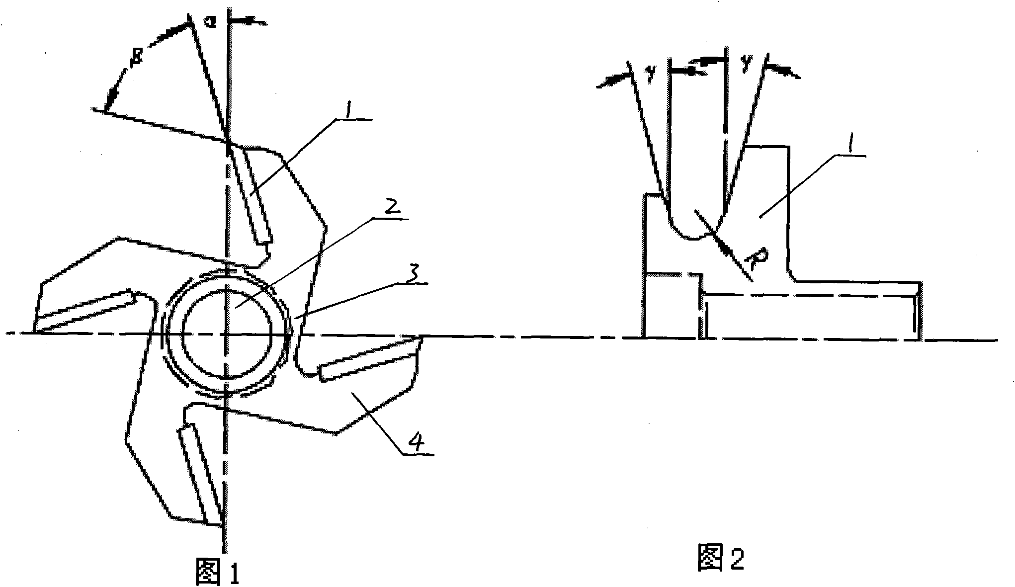
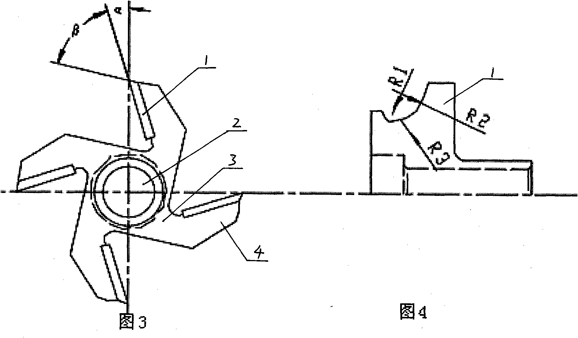
[0012] Such as figure 1 and figure 2 The illustrated embodiment 1 includes a cutter body 3 and a cutting tool 1 . The cutter body 3 is in the shape of a circular platform, and four slopes 4 are evenly distributed on the outer edge of one end end surface, and the ends of the slopes 4 have recesses, and the cutting knife 1 is welded on the recesses of the four slopes 4 respectively. Cutting knife 1 cutting edge is the circular arc that the radius that matches with cutting workpiece cutting circular arc is R. The two ends of the cutting knife 1 blade form an angle γ with the tangent of the two ends of the arc respectively, and γ is any angle less than or equal to 15°, which is convenient for entering and exiting the knife and processing workpieces with a little deformation on the edge. The front end face of the cutting blade 1 and the radial axis of the end face of the cutter body 3 form an angle α, where α is any angle between 5° and 8°. An angle β is formed between the end ...


PUM


Abstract

The invention discloses a moulding milling cutter. A cutter body is in a circular truncated cone shape; four inclined planes are evenly distributed at the outer edge of the end surface of one end part of the cutter body; a cutting tool is respectively fixed on concave platforms of the four inclined planes; the cutting edge of the cutting tool is in an arc shape matched with a cut arc shape of a cut workpiece; both ends of the cutting edge of the cutting tool respectively form an angle gamma (gamma is not greater than 15 degrees) with the tangent lines of two end circular arcs; the front end surface of the cutting edge of the cutting tool and a radial shaft of the end surface of the cutter body form an angle alpha (alpha is equal to 5-8 degrees); the middle part of the cutter body is provided with a penetrated counter bore; and a cutter shaft assorted with a machine tool is arranged in the counter bore. The invention ensures the processing precision and the surface finishment; the cutter body is in a counter bore structure of which the middle part is penetrated, can be clamped with a milling machine through the cutter shaft and is convenient to clamp; the arc processing of the workpiece can be completely finished by the milling machine of the milling cutter without manual operation, thereby shortening the processing time of the workpiece and improving the production efficiency.

Description

technical field [0001] The invention belongs to a face milling tool. Background technique [0002] In the production of core transformer coils and shell transformer reactor static ring substrates, the inner and outer peripheral contours must be processed into arcs or arcs composed of multiple arcs with different radii, and the arcs or arcs must be in accordance with the drawings strict control. At present, this process generally uses tools such as a bird plane to manually process the arc surface, and then grinds and repairs; or uses a hand-held electric tool such as a chamferer to chamfer both sides of the substrate, and then grinds and repairs to obtain the required arc surface or arc. shape. But no matter what kind of operation is adopted, a lot of manual work is required, which is time-consuming and labor-intensive, and it is difficult to process the arc surface or arc surface very accurately. Contents of the invention [0003] The present invention solves the above-...

Claims


Application Information

Patent Timeline
Patent Type & Authority Applications(China)
IPC IPC(8): B23C5/12
Inventor 任贵军黄少龙高秀珍张海宇
Owner BAODING TIANWEI BAOBIAN ELECTRICAL
Learn More