
Composite sliding seat matched with guide rail of machine tool

A composite, sliding seat technology, applied in the direction of large fixed members, metal processing machinery parts, metal processing equipment, etc., can solve problems such as single form

Inactive Publication Date: 2011-04-27
TDG MACHINERY TECH
View PDF5 Cites 2 Cited by
  • Summary
  • Abstract
  • Description
  • Claims
  • Application Information

AI Technical Summary

Problems solved by technology

[0006] The technical problem solved by the present invention is that, due to the relatively simple form of the sliding seat that cooperates with the guide rail on the existing machine tool, it is impossible to take into account that the static pressure sliding seat is not easy to wear and has a large bearing capacity and the stability of the plastic-coated sliding seat Higher and simple in structure, the advantages of these two aspects, and then provide a composite sliding seat that cooperates with the guide rail of the machine tool

Method used


Image

  • Composite sliding seat matched with guide rail of machine tool
  • Composite sliding seat matched with guide rail of machine tool

Examples


Embodiment Construction

[0014] The present invention will be described in further detail below in conjunction with the examples, but the protection scope of the present invention is not limited thereto.

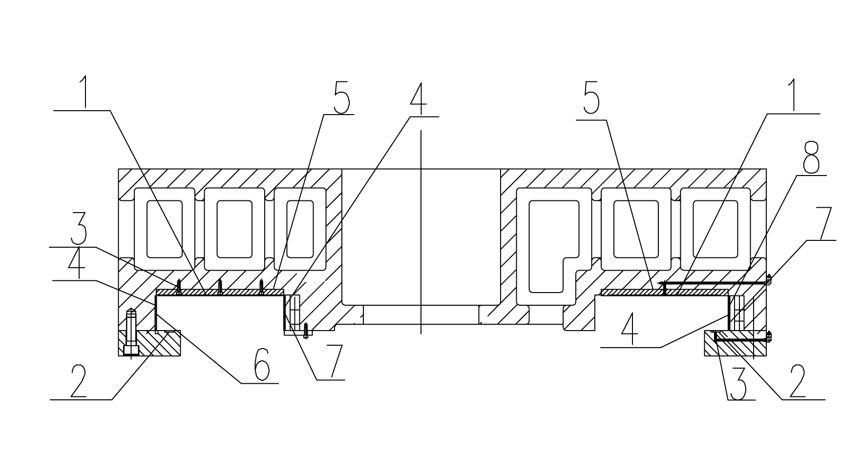
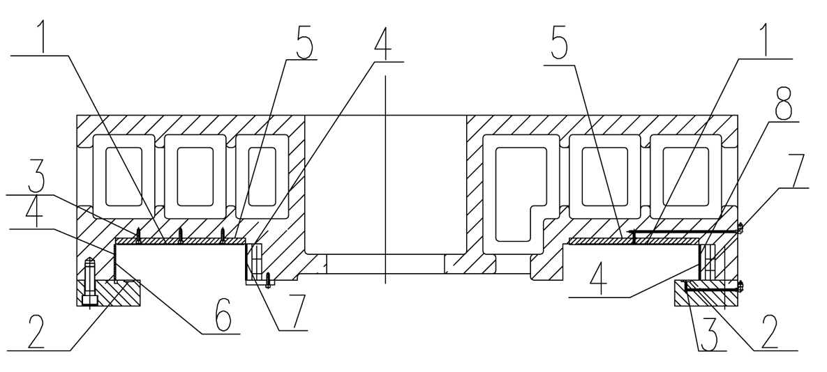
[0015] Such as figure 1 As shown, the present invention relates to a composite sliding seat that cooperates with machine tool guide rails. The sliding seat includes an upper supporting surface 1, a lower pressing plate surface 2 and side surfaces. The upper supporting surface 1 and the lower pressing plate surface 2 of the sliding seat are separated There is an oil cavity 3 for forming a static pressure fit between the guide rail and the sliding seat, and a plastic-coated layer 4 is provided on the side. The upper support surface 1 and the lower pressure plate surface 2 of the sliding seat are provided with an oil chamber 3, which is matched with the guide rail in the form of static pressure, so that there is no direct contact between the sliding seat and the working surface of the guide rail, basic...


PUM


Abstract

The invention relates to a composite sliding seat matched with a guide rail of a machine tool. The sliding seat comprises an upper supporting surface, a lower pressing plate surface and side faces, wherein the upper supporting surface and the lower pressing plate surface of the sliding seat are provided with oil cavities which make the guide rail and the sliding seat form a static pressure fit; and the side faces are provided with a plastic-attached layer respectively. The sliding seat combines the advantages of sliding seats in a static pressure form and in a plastic-attached mode, is low in friction coefficient, can make the driving power greatly reduced, is light and flexible in motion and has no crawling phenomenon at a low speed; working surfaces of the sliding seat and the guide rail are not directly contacted, abrasion hardly occurs, the original precision can be kept for a long time, the sliding seat has long service life, high bearing capacity, high rigidity and low frictional heating, the guide rail is low in temperature rise, the oil has vibration absorbing function, and the sliding seat is high in vibration resistance, simple in structure, high in stability, and convenient to machine, assemble, repair and adjust.

Description

technical field [0001] The invention belongs to the technical field of combined application of machine tool guide rails and sliding seats, and in particular relates to a composite sliding seat matched with machine tool guide rails. Background technique [0002] At present, the X-axis coordinates of the large-scale CNC floor boring produced by domestic and foreign manufacturers mainly adopt the sliding form of full static pressure, that is, the 7 working faces of the slider adopt the form of opening hydrostatic oil chambers. Such as Italy's PAMA, COLGAR, Japan's Toshiba, China's Qiqihar No. 2 Machine Tool Factory and Wuhan Heavy Machine Tool Factory, etc.; while Germany's SCHARMANN and China's Kunming Machine Tool Factory use a combination of plastic and rolling block unloading devices. sliding form. [0003] The static pressure sliding seat mainly means that lubricating oil with a certain pressure is input into the oil chamber on the working surface through a throttle to fo...

Claims


Application Information

Patent Timeline
IPC IPC(8): B23Q1/26B23Q1/38
Inventor 王谟吴昆高泽辉陈骝
Owner TDG MACHINERY TECH
Learn More