Laser cutting device and laser cutting method

A technology of laser cutting and cutting lanes, which is applied in glass cutting devices, glass manufacturing equipment, manufacturing tools, etc. It can solve the problems of low precision, small panels are prone to burrs, and it is difficult to meet the needs of industrial production, and achieve the effect of a wide detection range

Inactive Publication Date: 2011-04-27
FOXSEMICON INTEGRATED TECHNOLOGY (SHANGHAI) INC +1
View PDF1 Cites 5 Cited by
  • Summary
  • Abstract
  • Description
  • Claims
  • Application Information

AI Technical Summary

Problems solved by technology

[0003] In the prior art, when cutting a large panel, it is necessary to confirm whether the blind crack reaches a predetermined depth, for example, the blind crack usually needs to reach a predetermined depth, otherwise, when the small panel is separated mechanically or manually , the small panel is prone to burrs or other cutting marks (laser marks), resulting in low precision and difficult to meet the needs of industrial production

Method used


Image

  • Laser cutting device and laser cutting method
  • Laser cutting device and laser cutting method
  • Laser cutting device and laser cutting method

Examples


Embodiment Construction

[0016] The embodiments of the present invention will be described in further detail below in conjunction with the accompanying drawings.

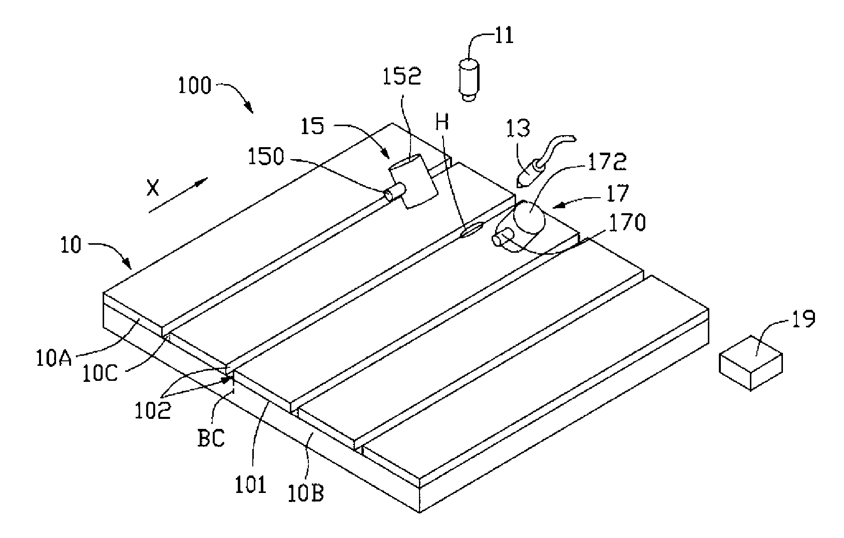
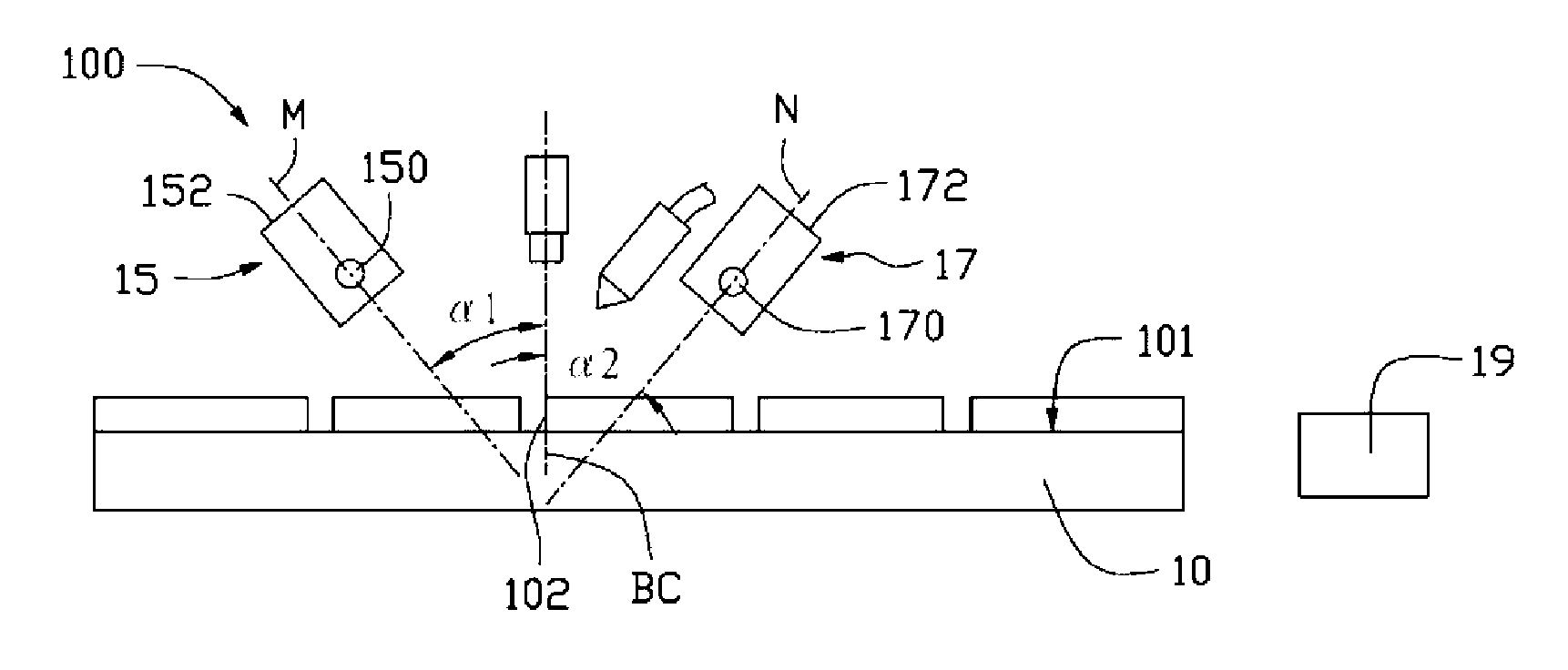
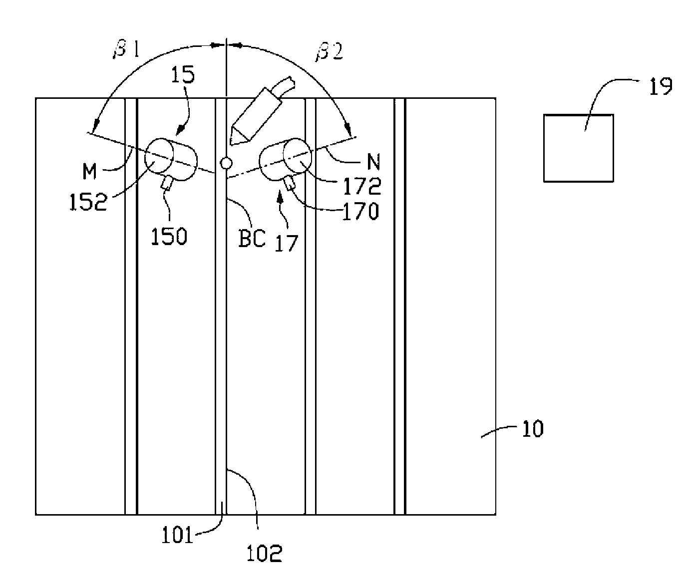
[0017] see figure 1 , a laser cutting device 100 provided by the first embodiment of the present invention is used to generate blind cracks BC on a panel 10 to be processed, so as to separate a plurality of substrates 10B from the blind cracks BC of the panel 10 . The panel 10 includes a substrate 10B, and a plurality of filter layers 10A distributed at intervals. Specifically, the substrate 10B has a surface to be processed 101, the plurality of filter layers 10A are formed on the surface 101 to be processed, the substrate 10B can be a glass substrate, and the plurality of filter layers 10A can be color filter layers respectively. Optical layer 10A. In addition, a cutting line 10C is formed between two adjacent filter layers 10A, and the two filter layers have two opposite sides 102 corresponding to the cutting line 10C, and the two side...


PUM


Abstract

The invention relates to a laser cutting device which comprises a laser generating unit, a cooling nozzle, a first image pick-up unit, a second image pick-up unit and an image processing unit. The laser generating unit is used for generating a laser beam. The cooling nozzle is used for generating a cooling medium. The first image pick-up unit comprises a first light source and a first image sensor, and the second image pick-up unit comprises a second light source and a second image sensor. The first light source and the second light source can selectively emit light beams, the light beams emitted by the first light source and the second light source are respectively irradiated on a blind crack from both opposite sides of the blind crack, and the first image sensor and the second image sensor are used for correspondingly sensing the light beams emitted by the first light source or the second light source and reflected on the blind crack to obtain the image of the blind crack. The imageprocessing unit is used for comparing the image of the blind crack with the image of a pre-stored reference blind crack to detect whether the blind crack reaches the preset depth or not.

Description

technical field [0001] The invention relates to a laser cutting device, in particular to a laser cutting device for cutting a panel, and a laser cutting method using the laser cutting device. Background technique [0002] During the manufacturing process of a flat display device, such as a liquid crystal display (Liquid Crystal Display, LCD), it is usually necessary to cut a large panel, such as a glass substrate, to obtain multiple small panels of required size. The above-mentioned cutting process generally includes the following steps: heating the large panel according to the size requirements of the small panel; cooling the heated area to generate blind cracks (blink crack), and separating the required small panel mechanically or manually. [0003] In the prior art, when cutting a large panel, it is necessary to confirm whether the blind crack has reached a predetermined depth, for example, the blind crack usually needs to reach a predetermined depth, otherwise, when the ...

Claims


Application Information

Patent Timeline
Patent Type & Authority Applications(China)
IPC IPC(8): C03B33/09
Inventor 周祥瑞何仁钦黄俊凯傅承祖
Owner FOXSEMICON INTEGRATED TECHNOLOGY (SHANGHAI) INC
Why Eureka
Try Eureka