Tractor load reversing clutch device

A clutch device and clutch technology, applied in the field of tractors, can solve the problems of high cost, complex structure, difficult manufacturing process, etc., and achieve the effects of increasing life, reducing drag torque, and saving axial space

Inactive Publication Date: 2011-04-27
CHINA YITUO GROUP
View PDF4 Cites 6 Cited by
  • Summary
  • Abstract
  • Description
  • Claims
  • Application Information

AI Technical Summary

Problems solved by technology

The above two types of reversing clutches have smaller axial dimensions and save space, but their structures are more complicated, the manufacturing process is more difficult, and the cost is higher

Method used


Image

  • Tractor load reversing clutch device
  • Tractor load reversing clutch device

Examples


Embodiment Construction

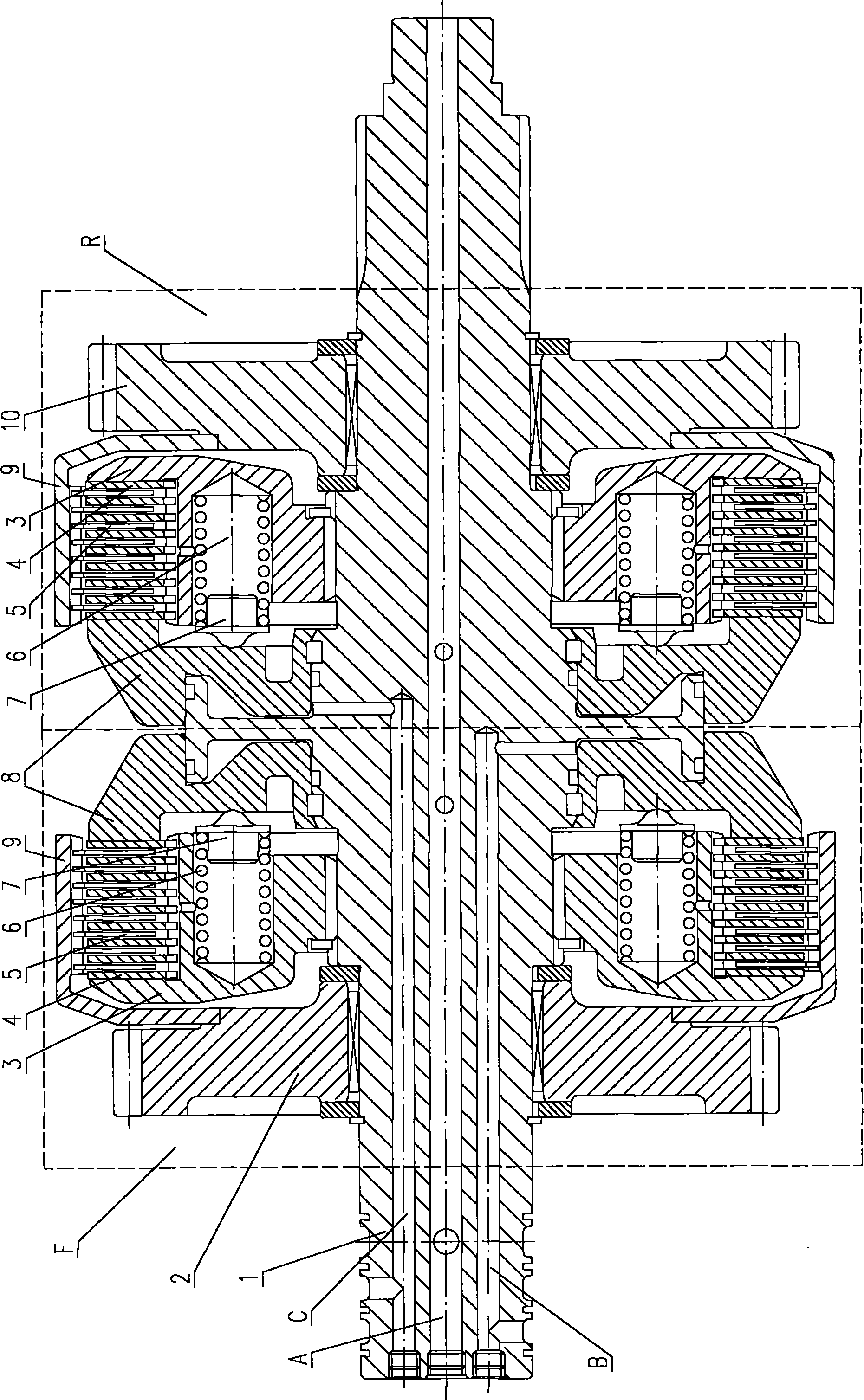
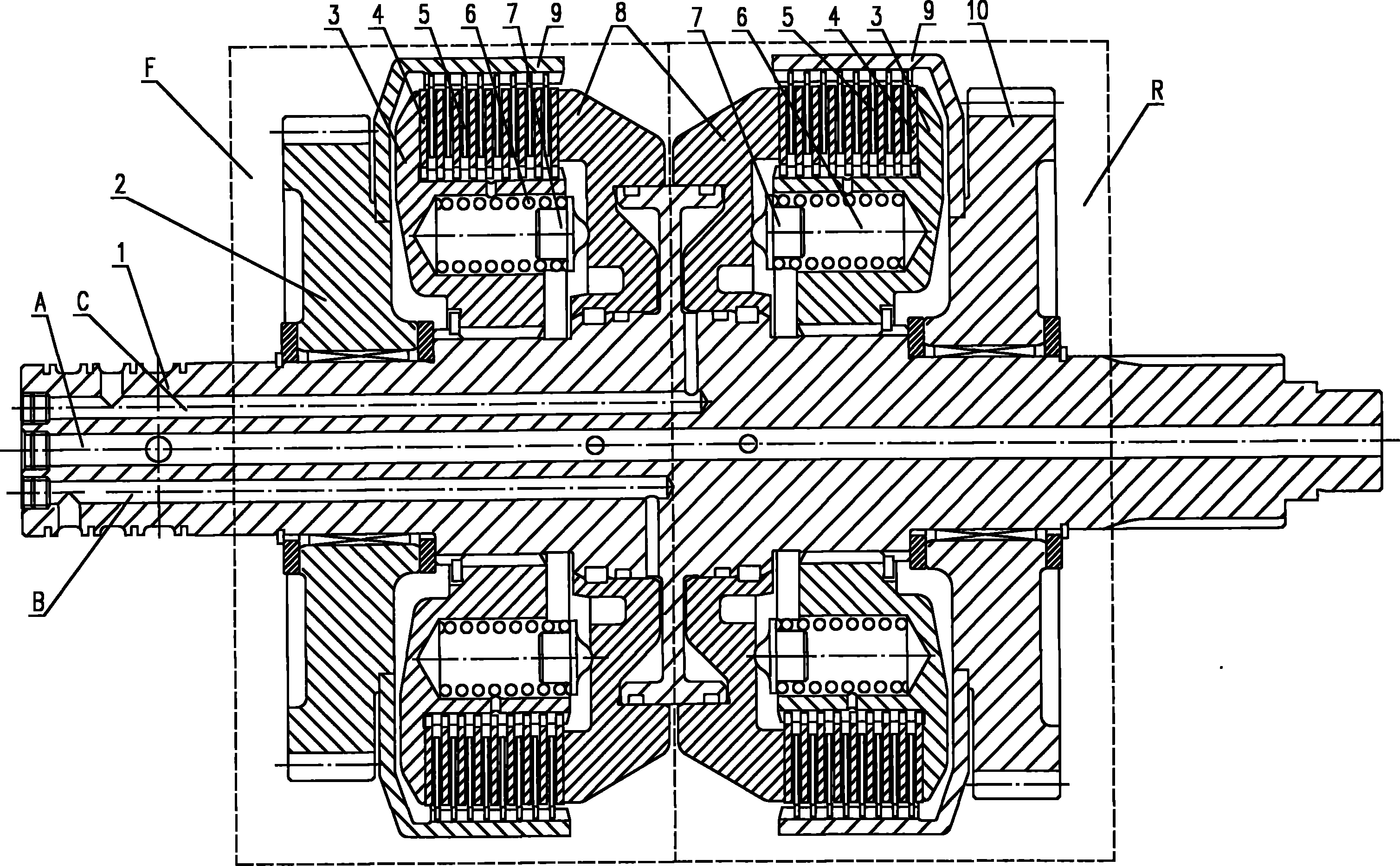
[0012] The present invention will be further described below in conjunction with the accompanying drawings. As shown in the accompanying drawings, the tractor load reversing clutch device includes a clutch shaft 1, a left input gear 2, a clutch hub 3, a clutch pressure plate 4, a clutch friction plate 5, a separation spring 6, a wear-reducing block 7, and a clutch piston 8 , clutch housing 9, right input gear 10. The left input gear 2, the clutch hub 3 and the clutch piston 8 are sequentially installed on the left half of the clutch shaft 1 to form the left clutch F, wherein the left input gear 2 and the clutch piston 8 are socketed with the clutch shaft 1, and the clutch hub 3 is connected with the clutch shaft 1 Fixed. The clutch piston 8, the clutch hub 3, and the right input gear 10 are sequentially installed on the right half of the clutch shaft 1 to form the right clutch R, wherein the right input gear 10 and the clutch piston 8 are socketed with the clutch shaft 1, and...


PUM


Abstract

The invention discloses a tractor load reversing clutch device. The device mainly comprises a clutch shaft, a left input gear, a clutch hub, a clutch pressure plate, a clutch friction plate, a release spring, an antifriction block, a clutch piston, a clutch shell and a right input gear. The left input gear, the clutch hub and the clutch piston are sequentially arranged on the left half part of the clutch shaft to form a clutch F, wherein the left input gear and the clutch piston are sleeved by a clutch shaft sleeve; and the clutch hub is fixedly connected with the clutch shaft. The clutch piston, the clutch hub and the right input gear are sequentially arranged on the right half part of the clutch shaft to form a right clutch R, wherein the right input gear and the clutch piston are sleeved by the clutch shaft sleeve; and the clutch hub is fixedly connected with the clutch shaft. The device is a left clutch and a right clutch. Because pressure oil paths are differently controlled, the service life of the clutch is prolonged. Under the action of the release spring, two oblique planes of the clutch shaft and the piston are closely attached, so that the device is automatically sealed and the dragging moment of the clutch is reduced.

Description

technical field [0001] The invention belongs to the field of tractors, and relates to a tractor clutch device, in particular to a tractor load reversing clutch device. Background technique [0002] At present, in the gearboxes of high-power wheeled tractors produced in my country, the reverse gears mostly use mechanical shifting methods such as sliding gears, meshing sleeves, and synchronizers to switch the driving direction of the tractor. When the tractor changes the driving direction, it needs to disengage the clutch to cut off the engine power first, and then switch the corresponding gears, which is slow to change gears and affects the working efficiency. However, most foreign high-power wheeled tractors use load-reversing gearboxes, that is, when switching between forward and reverse gears, the gear shifting operation is performed directly without cutting off the engine power, and the shifting efficiency is high. [0003] The tractor must be equipped with a correspondi...

Claims


Application Information

Patent Timeline
Patent Type & Authority Applications(China)
IPC IPC(8): F16D25/10F16D25/0638F16C3/02F16N1/00
CPCF16D2021/0661F16D21/04F16D25/0638F16D25/10
Inventor 王东青冯春凌郭志强赵考田王富凯
Owner CHINA YITUO GROUP
Why Eureka
Try Eureka