Fin structure

A technology of fins and small channels, applied in the field of fin structures, can solve the problems of reduced heat exchange, uneven distribution of heat exchange efficiency and flow velocity, and can not be eliminated, and achieves compactness of the device and excellent heat exchange. Effect of performance, heat exchange performance improvement

Inactive Publication Date: 2011-04-27
USUI KOKUSAI SANGYO KAISHA LTD
View PDF3 Cites 5 Cited by
  • Summary
  • Abstract
  • Description
  • Claims
  • Application Information

AI Technical Summary

Problems solved by technology

Moreover, the small channels separated by the plate fins composed of a single metal sheet form independent channels without communicating with each other, so once the flow velocity distribution is not uniform, it cannot be eliminated
Thus, the problem of flow down cannot be solved that the heat exchange efficiency is greatly reduced due to the non-uniform distribution of the flow velocity
In addition, the distribution of fluid in the small channels divided into heat transfer tubes is not uniform. This unevenness makes it impossible to cool

Method used


Image

  • Fin structure
  • Fin structure
  • Fin structure

Examples


Embodiment 1

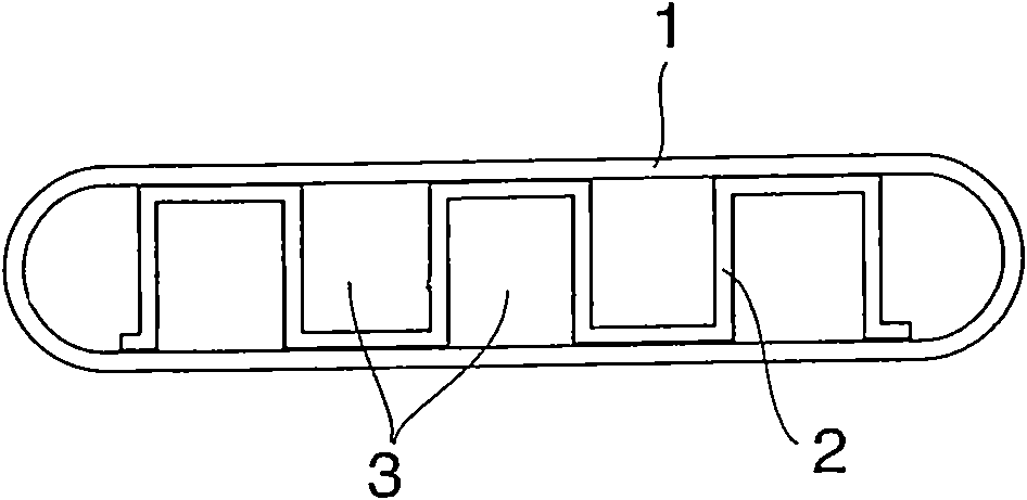
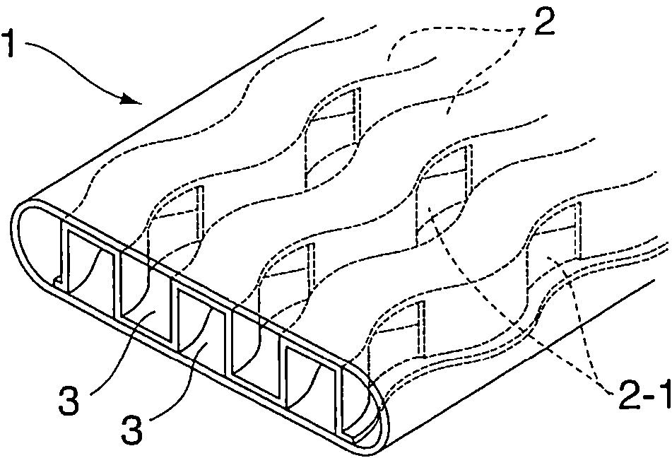
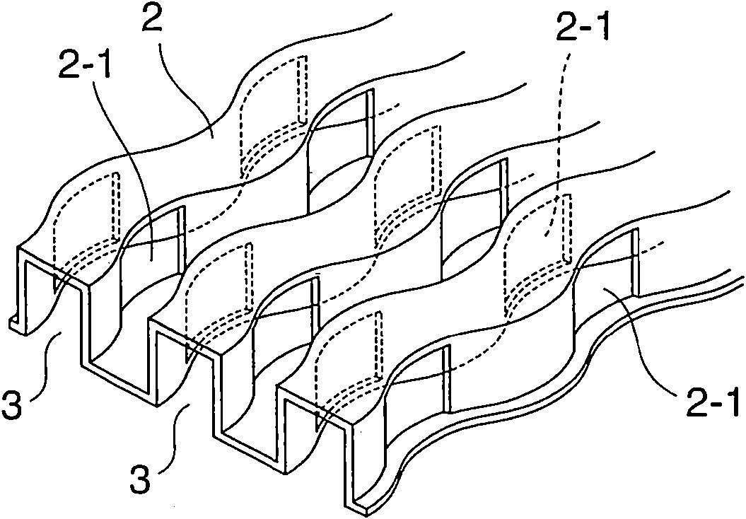
[0042] In the plate fin according to the first embodiment of the present invention, as attached Figure 1A and 1BAs shown, a plurality of plate parts are obtained by processing a thin plate made of austenitic stainless steel SUS304 with a thickness of 0.2 mm into a square of a predetermined size, and by punching 8 sheets of the plate part by means of a punch A predetermined cut 2-1 is formed. The plate part is then molded to produce a fin structure 2, which has a rectangular cross-section, corrugated in the longitudinal direction, and has a plurality of cutouts 2-1 in its sides, as shown in the attached figure 2 shown. The fin structure 2 obtained in this way was inserted into a flat heat transfer tube 1 consisting of the same material and having a thickness of 0.5 mm. The fin structure 2 is connected into an integral structure with solder so as to divide it into a plurality of small channels 3 having a square cross-section in the flat heat transfer tube 1 and having corru...

Embodiment 2

[0047] as attached Figure 4 As shown, a corrugated fin structure 2a similar to that in Example 1 was prepared, except that a circular through hole 4 was formed to replace the incision 2-1 in the side wall of the small channel 3a formed by the fin structure 2a in Example 1. . Like the fin structure of Example 1, the obtained fin structure 2a is integrally connected with the flat heat transfer tubes in a similar manner, so as to obtain 8 flat heat transfer tubes 1a of the heat exchanger, each of the heat transfer tubes Both have fin structure 2a, as attached Figure 4 shown. Then, as in Example 1, the heat transfer pipe 1a was assembled into an EGR cooling device, and it was subjected to a cooling test under the same conditions as in Example 1. The results show that the cooling efficiency is substantially equal to that of Example 1.

Embodiment 3

[0049] as attached Image 6 As shown, a fin structure 2b similar to that of Example 2 was prepared except that the shape of the plate material in the longitudinal direction was linear. The method used here to prepare the fin structure 2b does not require any complicated molding process, but a simple stamping process such as punching the through hole 4a is sufficient, so that the cost of manufacturing the fin structure 2b can be greatly reduced. Like the fin structure of Embodiment 2, the fin structure 2b is inserted into the flat heat transfer tube and integrally connected in a similar manner to manufacture 8 flat heat transfer tubes 1b, each of which has a set In which the fin structure 2b, as attached Figure 5 shown. Then, as in Example 2, the heat transfer tube 1b was assembled into an EGR gas cooling device, and a cooling test was performed on it under the same conditions. The results show that: the heat exchange efficiency is slightly lower than that of Example 2, but...


PUM

PropertyMeasurementUnit
Thicknessaaaaaaaaaa

Abstract

The invention discloses a fin structure disposed in heat transfer pipe, which divides the fluid channel into a plurality of small channels. The fluid includes cooling medium or refrigerant flowing in a heat transfer pipe; the cross sections of the small channels of the fin structure are squares or rectangles; the longitudinal plane of the small channels of the fin structure are corrugated shaped with same corrugation width; at least one rising section is formed on the side surface, or upper wall, or lower wall of the small channel of the fin structure, in order that at least one rising section is formed extending toward the upstream of the small channel by a tongue shape.

Description

[0001] The parent case of the application of the present invention is: the application date is September 8, 2005, the application number is 200510113221.0, and the name is "fin structure, heat transfer tube provided with the fin structure, and heat exchange tube equipped with the heat transfer tube." Device" application for invention. technical field [0002] The present invention relates to a fin structure for agitating fluid in a heat exchanger, and more particularly, the present invention relates to a fin structure arranged in a heat transfer tube of a heat exchange type cooling device for generating agitation, Turbulence or eddy flow is formed in the cooled medium fluid or refrigerant fluid flowing in the heat transfer tube, thereby increasing the contact between the heat transfer tube wall and the fluid. Moreover, the fin structure is also used to make the flow rate or flow rate of the fluid flowing in the heat transfer tube uniform, so as to achieve excellent heat exchan...

Claims


Application Information

Patent Timeline
IPC IPC(8): F28F3/00F28F13/12
CPCF28D21/0003F28D7/1684F28F3/025F28D2021/0082F28F3/027F28F2250/04F28D7/10F28F1/00F28F1/02F28F1/04
Inventor 臼井正一郎后藤忠弘
Owner USUI KOKUSAI SANGYO KAISHA LTD
Why Eureka
Try Eureka