Fin structure
A fin and small channel technology, applied in the field of fin structure, can solve the problems of reduced heat exchange, inability to eliminate, uneven distribution of heat exchange efficiency and flow velocity, etc. The effect of improved, excellent heat exchange performance
- Summary
- Abstract
- Description
- Claims
- Application Information
AI Technical Summary
Problems solved by technology
Method used
Image
Examples
Embodiment 1
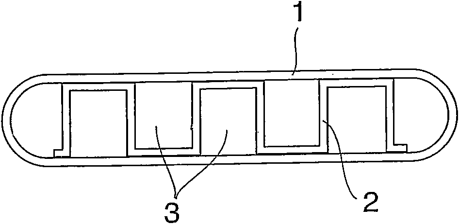
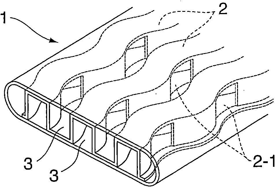
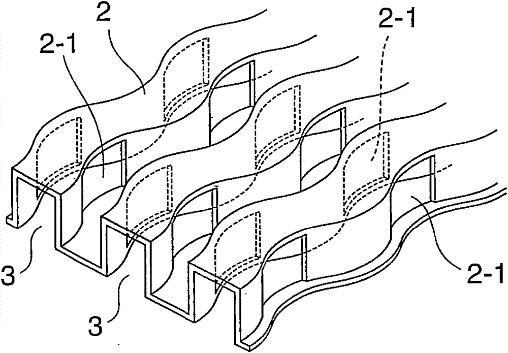
[0042] In the plate fin according to the first embodiment of the present invention, as attached Figure 1A and 1BAs shown, a plurality of plate parts are obtained by processing a thin plate made of austenitic stainless steel SUS304 with a thickness of 0.2 mm into a square of a predetermined size, and by punching 8 sheets of the plate part by means of a punch A predetermined cut 2-1 is formed. The plate part is then molded to produce a fin structure 2, which has a rectangular cross-section, corrugated in the longitudinal direction, and has a plurality of cutouts 2-1 in its sides, as shown in the attached figure 2 shown. The fin structure 2 obtained in this way was inserted into a flat heat transfer tube 1 consisting of the same material and having a thickness of 0.5 mm. The fin structure 2 is connected into an integral structure with solder so as to divide it into a plurality of small channels 3 having a square cross-section in the flat heat transfer tube 1 and having corru...
Embodiment 2
[0047] as attached Figure 4 As shown, a corrugated fin structure 2a similar to that in Example 1 was prepared, except that a circular through hole 4 was formed to replace the incision 2-1 in the side wall of the small channel 3a formed by the fin structure 2a in Example 1. . Like the fin structure of Example 1, the obtained fin structure 2a is integrally connected with the flat heat transfer tubes in a similar manner, so as to obtain 8 flat heat transfer tubes 1a of the heat exchanger, each of the heat transfer tubes Both have fin structure 2a, as attached Figure 4 shown. Then, as in Example 1, the heat transfer pipe 1a was assembled into an EGR cooling device, and it was subjected to a cooling test under the same conditions as in Example 1. The results show that the cooling efficiency is substantially equal to that of Example 1.
Embodiment 3
[0049] as attached Image 6 As shown, a fin structure 2b similar to that of Example 2 was prepared except that the shape of the plate material in the longitudinal direction was linear. The method used here to prepare the fin structure 2b does not require any complicated molding process, but a simple stamping process such as punching the through hole 4a is sufficient, so that the cost of manufacturing the fin structure 2b can be greatly reduced. Like the fin structure of Embodiment 2, the fin structure 2b is inserted into the flat heat transfer tube and integrally connected in a similar manner to manufacture 8 flat heat transfer tubes 1b, each of which has a set In which the fin structure 2b, as attached Figure 5 shown. Then, as in Example 2, the heat transfer tube 1b was assembled into an EGR gas cooling device, and a cooling test was performed on it under the same conditions. The results show that: the heat exchange efficiency is slightly lower than that of Example 2, but...
PUM
 Abstract
Description
Claims
Application Information
 - R&D
- Intellectual Property
- Life Sciences
- Materials
- Tech Scout
- Unparalleled Data Quality
- Higher Quality Content
- 60% Fewer Hallucinations
Browse by: Latest US Patents, China's latest patents, Technical Efficacy Thesaurus, Application Domain, Technology Topic, Popular Technical Reports.
© 2025 PatSnap. All rights reserved.Legal|Privacy policy|Modern Slavery Act Transparency Statement|Sitemap|About US| Contact US: help@patsnap.com


