Method for measuring relative rotation angle and relative rotation speed of two rotors of coaxial dual rotor motor and sensor for implementing same
A dual-rotor motor and rotor angle technology, which is applied to devices, measuring devices, and instruments using electric/magnetic methods, can solve problems such as signal lag and measurement result errors, and achieve the effect of suppressing high-frequency noise.
- Summary
- Abstract
- Description
- Claims
- Application Information
AI Technical Summary
Problems solved by technology
Method used
Image
Examples
specific Embodiment approach 1
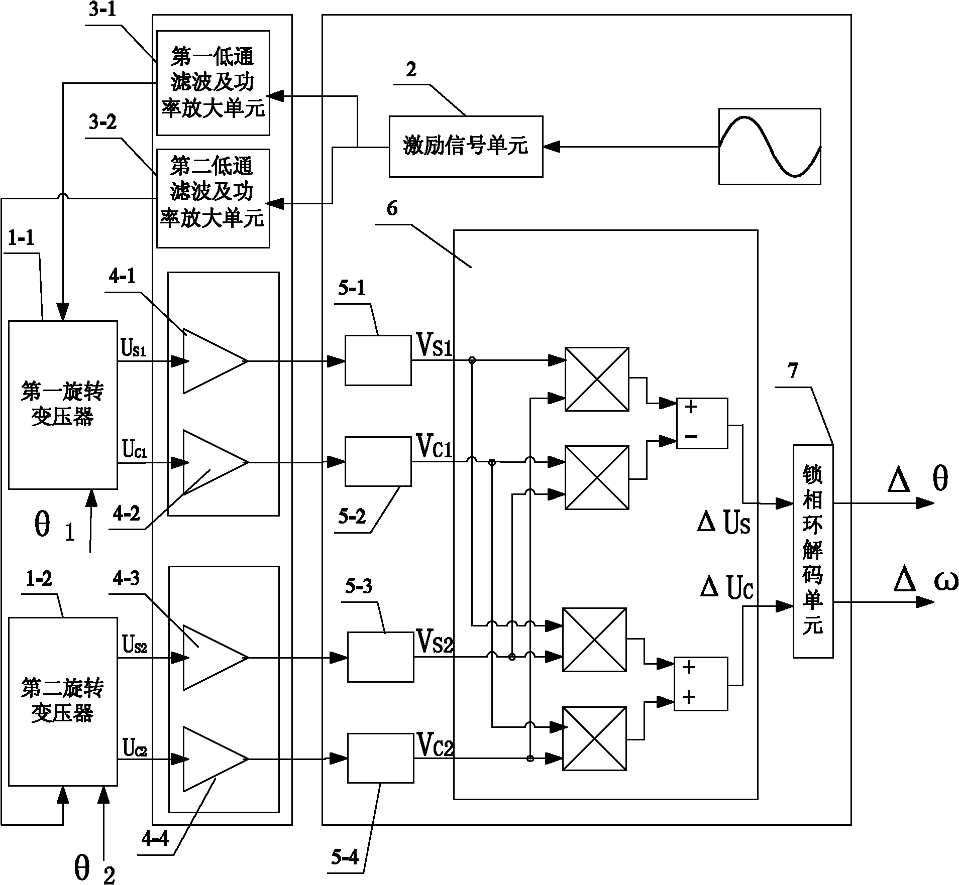
[0037] Specific implementation mode one: the following combination figure 1 Describe this embodiment, the method for measuring the relative rotation angle and rotational speed of two rotors of a coaxial dual-rotor motor described in this embodiment,
[0038] Install the first rotary transformer 1-1 and the second rotary transformer 1-2 concentrically on the shafts of the two rotors of the dual-rotor motor respectively, and the rotor angle signal obtained by the first rotary transformer 1-1 is θ 1 , the rotor angle signal obtained by the second resolver 1-2 is θ 2 ;
[0039]The excitation windings of the two rotary transformers input excitation signals of the same frequency and phase: the excitation signal U input by the first rotary transformer 1-1 EXC1 =E 1 cos(ω e t), where E 1 is the amplitude of the excitation signal of the first resolver 1-1, ω e is the angular frequency of the excitation signal, t is the time,
[0040] The excitation signal U input by the second ...
specific Embodiment approach 2
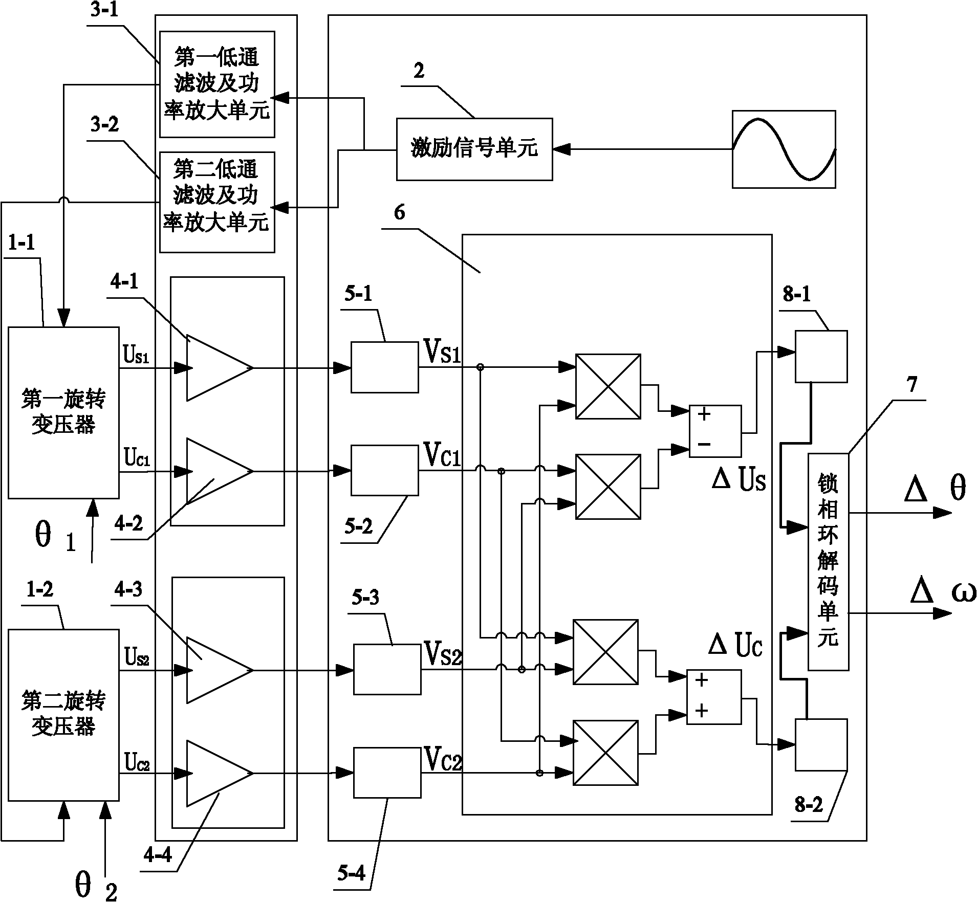
[0080] Specific implementation mode two: the following combination figure 2 Describe this embodiment, this embodiment is a further description of Embodiment 1, the V S1 , V C1 , V S2 and V C2 After coordinate transformation, the obtained ΔU S and ΔU C After low-pass filtering respectively, ignoring the phase shift and attenuation of the low-frequency signal, the expression of the output signal is transformed into:
[0081]
[0082] ΔU' S and ΔU′ C is the carrier-free modulation signal of the relative rotation angle of the two rotors, and then ΔU′ S and ΔU′ C Solve the phase-locked loop circuit.
[0083] In this embodiment, the spectrum shift and coordinate transformation of the signal are completed at the same time, and ΔU S and ΔU C After low-pass filtering respectively, the input signal of the phase-locked loop decoding circuit does not contain high-frequency components of constant frequency, which can improve the robustness of the system.
specific Embodiment approach 3
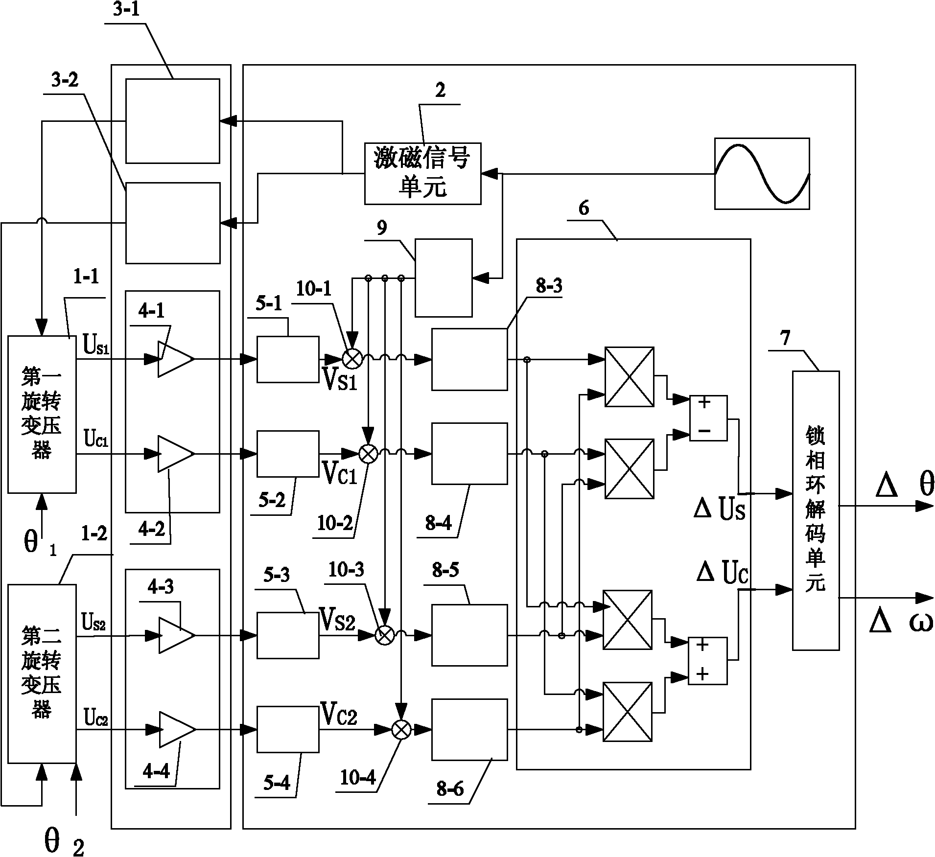
[0084] Specific implementation mode three: the following combination image 3 This embodiment is described. This embodiment is a further description of Embodiment 1. In this embodiment, the excitation signal is used to shift the frequency spectrum of the output signal to realize the demodulation of four output signals of two resolvers. According to the excitation of two resolvers The signals have the same frequency and phase, and the phase shifts introduced after signal conditioning are equal, then Choose the compensation phase β such that will V S1 , V C1 , V S2 and V C2 After multiplication with the excitation signal with phase shift angle β respectively, we get:
[0085]
[0086]
[0087]
[0088]
[0089] where V' S1 is the signal after the spectrum shift of the sinusoidal winding output signal of the first rotary transformer 1-1, V' C1 is the signal after the cosine winding of the first rotary transformer 1-1 has shifted the frequency spectrum of the ...
PUM
 Abstract
Description
Claims
Application Information
 - R&D
- Intellectual Property
- Life Sciences
- Materials
- Tech Scout
- Unparalleled Data Quality
- Higher Quality Content
- 60% Fewer Hallucinations
Browse by: Latest US Patents, China's latest patents, Technical Efficacy Thesaurus, Application Domain, Technology Topic, Popular Technical Reports.
© 2025 PatSnap. All rights reserved.Legal|Privacy policy|Modern Slavery Act Transparency Statement|Sitemap|About US| Contact US: help@patsnap.com


