Method for improving monitoring distance of single-core feedback optical fiber sensing technology and optical fiber interference structure

An optical fiber sensing technology and optical fiber interference technology, applied in the field of optical fiber interference structure, which can solve the problems of system measurement capability limitation, signal interference, and inability to distinguish signals.

Active Publication Date: 2011-04-27
FUDAN UNIV
View PDF2 Cites 8 Cited by
  • Summary
  • Abstract
  • Description
  • Claims
  • Application Information

AI Technical Summary

Problems solved by technology

[0013] exist figure 2 In this structure, there are usually idle ports, such as port 7b. If an optical path similar to that connected to port 7a is connected behind it, the interference formed by the optical path at the rear end of port 7a and port 7b will be aliased and cannot be distinguished. Which port is connected to the signal picked up by the optical path, and the signals interfere with each other, and the normal demodulation of the phase difference of the interference signal cannot be performed. Especially in long-distance monitoring, the location of the disturbance cannot be determined, and the measurement capability of the system is limited.

Method used


Image

  • Method for improving monitoring distance of single-core feedback optical fiber sensing technology and optical fiber interference structure
  • Method for improving monitoring distance of single-core feedback optical fiber sensing technology and optical fiber interference structure
  • Method for improving monitoring distance of single-core feedback optical fiber sensing technology and optical fiber interference structure

Examples


Embodiment Construction

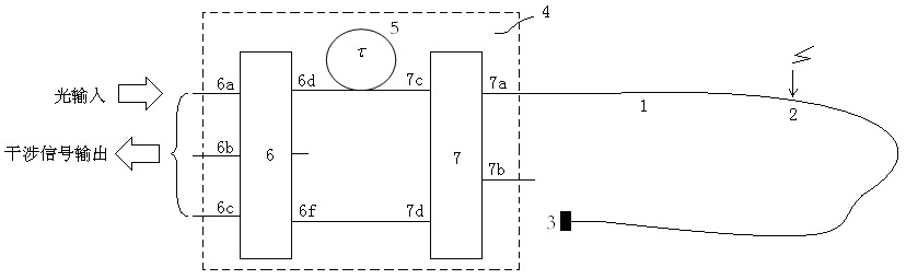
[0051] In this embodiment, the use of Figure 5 The interference structure shown is used for distributed long-distance positioning monitoring of pipelines. The light source is a superluminescence diode (SLD) with a center wavelength of 1300nm produced by the 44 Research Institute of the Electronics Group Corporation. The optical fiber coupler is produced by Wuhan Institute of Posts and Telecommunications. 12 is a 3*3 split coupler, and 13 is a 2*2 split coupler. The optical fiber used in the optical fiber delay line is Corning's G652 single-mode optical fiber. In order to isolate external noise interference, optical fiber interference components are placed in sound insulation equipment. Two optical cables are used as inductive optical cables for picking up disturbance signals, respectively laid along the pipelines to be monitored, one optical cable is connected to the port 13a1, and a reflector is connected at the end; the other optical cable is connected to the port 13a2, ...


PUM


Abstract

The invention belongs to the technical field of the optical fiber sensing technology, and particularly relates to a method for improving the monitoring distance of the single-core feedback optical fiber sensing technology and an optical fiber interference structure. The method comprises the following steps that: two mutually-independent optical fibers are connected to a common optical fiber interference assembly, and the two optical fibers share a light path of the optical fiber interference assembly, so that each optical fiber forms an integral interference structure together with a feedbackdevice at the tail end of each optical fiber and the optical fiber interference assembly; a phase modulation device is connected in series on one of the optical fibers, a modulation signal is appliedto the light path from the phase modulation device, and an interference signal generated by the path of optical fiber is separated from that generated by the other signal of optical fiber by selecting an operating point of the modulation signal to achieve the effect of the multiplication of the monitoring distance. In the method, only one carrier wave is applied, the setting flexibility of modulation parameters is large, and signal separation is complete and easy to realize. The method is particularly suitable for long-distance pipeline monitoring, the large-range peripheral security protection of optical fibers and the like.

Description

technical field [0001] The invention belongs to the technical field of optical fiber sensing, and in particular relates to a method for improving the monitoring distance of single-core feedback optical fiber sensing technology and an optical fiber interference structure. Background technique [0002] With the development of science and technology, the importance of security precautions has become more and more prominent. Some important military secret departments, military locations, banks, airports, etc. have higher and higher demands for large-scale, long-distance, and high-reliability security technologies. . The rise and development of optical fiber sensing technology provides more attractive solutions for these application requirements. Today, more and more types of optical fiber technology are applied to safety protection technology. It has many characteristics and advantages: no power supply is required for the sensing end, strong anti-interference and high reliabili...

Claims


Application Information

Patent Timeline
IPC IPC(8): G01S11/12G02F1/01G02B6/26
Inventor 贾波肖倩
Owner FUDAN UNIV
Why Eureka
Try Eureka