Ground comprehensive wire slot structure

A trunking and ground technology, applied in the fields of science, construction, and decoration engineering, can solve problems such as difficult cleaning and maintenance, large space occupation, and difficulty in leveling, and achieve the effect of flexible power supply and small space occupation

Inactive Publication Date: 2011-04-27
GUANGZHOU DESIGN INST
View PDF4 Cites 2 Cited by
  • Summary
  • Abstract
  • Description
  • Claims
  • Application Information

AI Technical Summary

Problems solved by technology

[0004] The purpose of the present invention is to overcome the unavoidable problems caused by laying under the raised floor or laying wire ducts on the ground (floor), solve the problems of large space occupation, difficulty in cleaning and maintenance, and difficulty in leveling, and avoid the harm of rodents and insects , and realize the ground integrated wire slot structure with measures such as flexible power intake and interference shielding at cross laying places

Method used


Image

  • Ground comprehensive wire slot structure
  • Ground comprehensive wire slot structure
  • Ground comprehensive wire slot structure

Examples


specific Embodiment 1

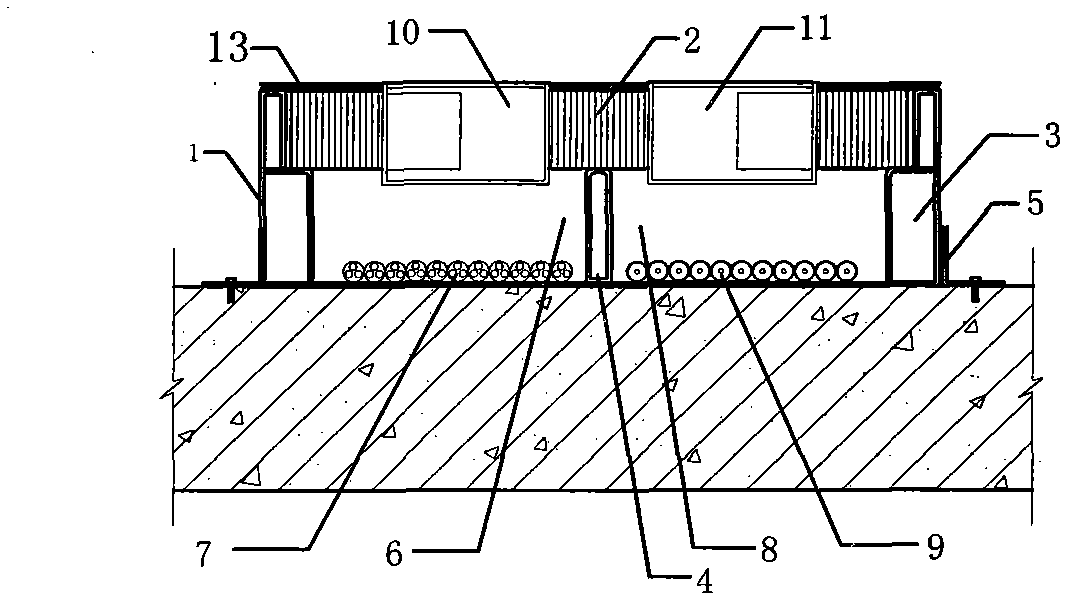
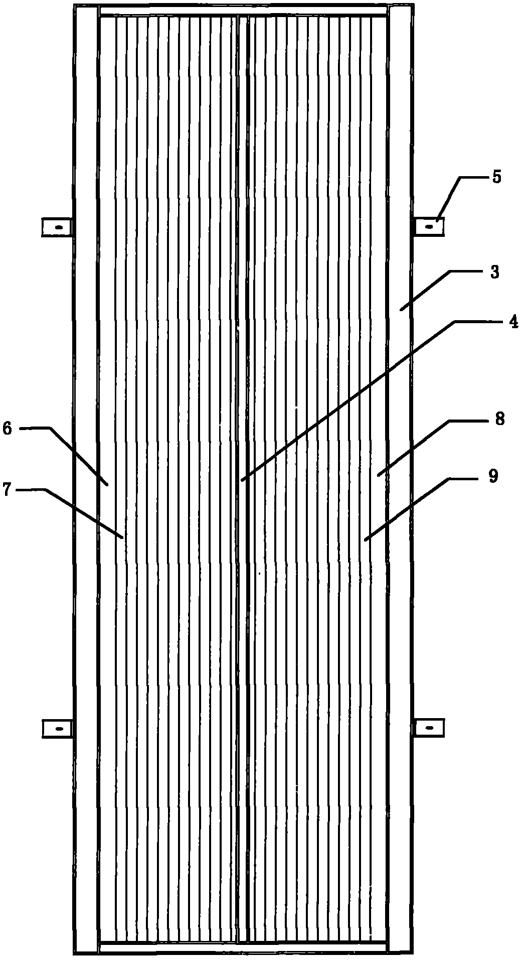
[0026] figure 1 and figure 2 Constitute the specific embodiment 1 of the present invention.

[0027] refer to figure 1 , figure 2 , this embodiment includes a base 1 and a cover plate 2, and a load-bearing frame 3 is respectively provided on both sides of the base 1, and the lower part of the load-bearing frame 3 forms an easy-to-assemble and detachable connection structure with the base 1 through a positioning attachment 5, and the load-bearing The upper part of the frame 3 and the cover plate 2 form an easy-to-assemble and disassemble connection structure; between the two load-bearing frames 3, the base 1, the cover plate 2 and the load-bearing frame 3 form a closed structure that is easy to assemble and disassemble. Plate 4 is divided into strong wire groove 6, weak wire groove 8, described strong wire groove 6, weak wire groove 8 are provided with strong electric cable 7, weak electric cable 9 respectively; Corresponding to 8, several strong electric sockets 10 and w...

specific Embodiment 2

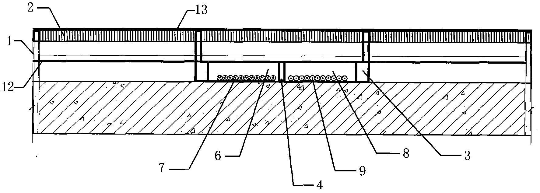
[0029] image 3 and Figure 4 Constitute the specific embodiment 2 of the present invention.

[0030] refer to image 3 , Figure 4 , composed of base 1, cover plate 2 and load-bearing frame 3 to form an easy-to-assemble and disassemble closed structure, which is an upper and lower two-layer structure, the upper layer and the lower layer intersect at right angles, forming a right-angled cross-shaped upper and lower layer structure; the upper layer and the lower layer A layer partition 12 is provided at the joint, and the function of the layer partition 12 is to isolate the upper and lower layers from interference. Each layer is divided into a strong wire slot 6 and a weak wire slot 8 respectively by the support inter-plate 4 arranged therein, and the strong wire slot 6 and the weak wire slot 8 are respectively provided with a strong electric cable 7 and a weak electric cable 9; and The strong electric wire slot 6 and the weak electric wire slot 8 correspond, and several st...

specific Embodiment 3

[0031] Figure 5 and Figure 6 Constitute the specific embodiment 3 of the present invention.

[0032] refer to Figure 5 , Figure 6 , which is surrounded by base 1, cover plate 2 and load-bearing frame 3 to form an easy-to-assemble and disassemble closed structure. It is an upper and lower two-layer structure. The upper layer and the lower layer intersect at right angles. It is superimposed on the lower layer to form a through-turn cross-type upper and lower layer structure; a layer partition 12 is provided at the connection between the upper layer and the lower layer. All the other are with specific embodiment 2.


PUM


Abstract

The invention relates to a ground comprehensive wire slot structure which comprises a base (1) and a cover plate (2), and is characterized in that the two sides of the base (1) are respectively provided with a bearing frame (3); the lower parts of the bearing frames (3) and the base (1) form an easy-assembly/disassembly connection structure through a positioning accessory (5); the upper parts of the bearing frames (3) and the cover plate (2) form an easy-assembly/disassembly connection structure; and an easy-assembly/disassembly closed structure is defined by the base (1), the cover plate (2) and the bearing frames (3), is positioned between the two bearing frames (3), and is divided into a strong-current wire slot (6) and a weak-current wire slot (8) by a support partition plate (4) arranged in the closed structure. Through the invention, the ground comprehensive wire slot structure can directly bear the load, or can be changed freely and flexibly through the cover plate and randomly combined, arranged and fixedly mounted according to the site situation, thereby being very simple and convenient; and moreover, the power can be flexibly gotten, and measures for shielding interference and the like are taken on the intersection laying positions.

Description

technical field [0001] The invention relates to a cable laying device structure, in particular to a ground integrated wire groove structure, which belongs to the fields of construction, decoration engineering and science and technology. Background technique [0002] Today's society is developing very rapidly. In addition to ordinary cables, modern office buildings also need to be equipped with broadband and optical fiber cables to take advantage of the convenience of the Internet to improve work efficiency; Cables and network cables, for the sake of indoor beauty and avoiding the messy setting of cables, it is necessary to set up ground wire troughs in order to follow the trend of the times; setting various cables in the ground wire troughs can ensure that they are available at a certain distance. The power supply, communication and information network used will not stumble pedestrians and make it easier to pass through with trolleys. [0003] At present, there are generall...

Claims


Application Information

Patent Timeline
Patent Type & Authority Applications(China)
IPC IPC(8): H02G3/04
Inventor 胡毅李福安
Owner GUANGZHOU DESIGN INST
Why Eureka
Try Eureka