Voltage-to-current converter

A current converter and voltage technology, applied in the direction of electrical components, automatic power control, etc., can solve the problems of phase-locked loop frequency increase, limitation, and the inability to use low-voltage MOS tubes for current-controlled oscillators, so as to reduce the current The effect of dithering, increasing the frequency

Inactive Publication Date: 2011-04-27
SHANGHAI INTEGRATED CIRCUIT RES & DEV CENT
View PDF3 Cites 12 Cited by
  • Summary
  • Abstract
  • Description
  • Claims
  • Application Information

AI Technical Summary

Problems solved by technology

However, the super source follower of the voltage-current converter in the prior art needs to increase the input control voltage Vctrl by one Vgs, so that the output voltage of the voltage-current converter will greatly exceed 1V, so that the current-controlled oscillator ( ICO) cannot use low-voltage MOS tubes, which limits the frequency increase of the phase-locked loop (PLL), and cannot reflect the advantages of advanced technology
[0006] In summary, it can be seen that the voltage-to-current converters of the prior art have the problem that the output voltage is large, so that the current-controlled oscillation circuit cannot use a low-voltage MOS tube. Therefore, it is necessary to propose an improved technical means to solve this problem.

Method used


Image

  • Voltage-to-current converter
  • Voltage-to-current converter
  • Voltage-to-current converter

Examples


Embodiment Construction

[0020] The implementation of the present invention is described below through specific examples and in conjunction with the accompanying drawings, and those skilled in the art can easily understand other advantages and effects of the present invention from the content disclosed in this specification. The present invention can also be implemented or applied through other different specific examples, and various modifications and changes can be made to the details in this specification based on different viewpoints and applications without departing from the spirit of the present invention.

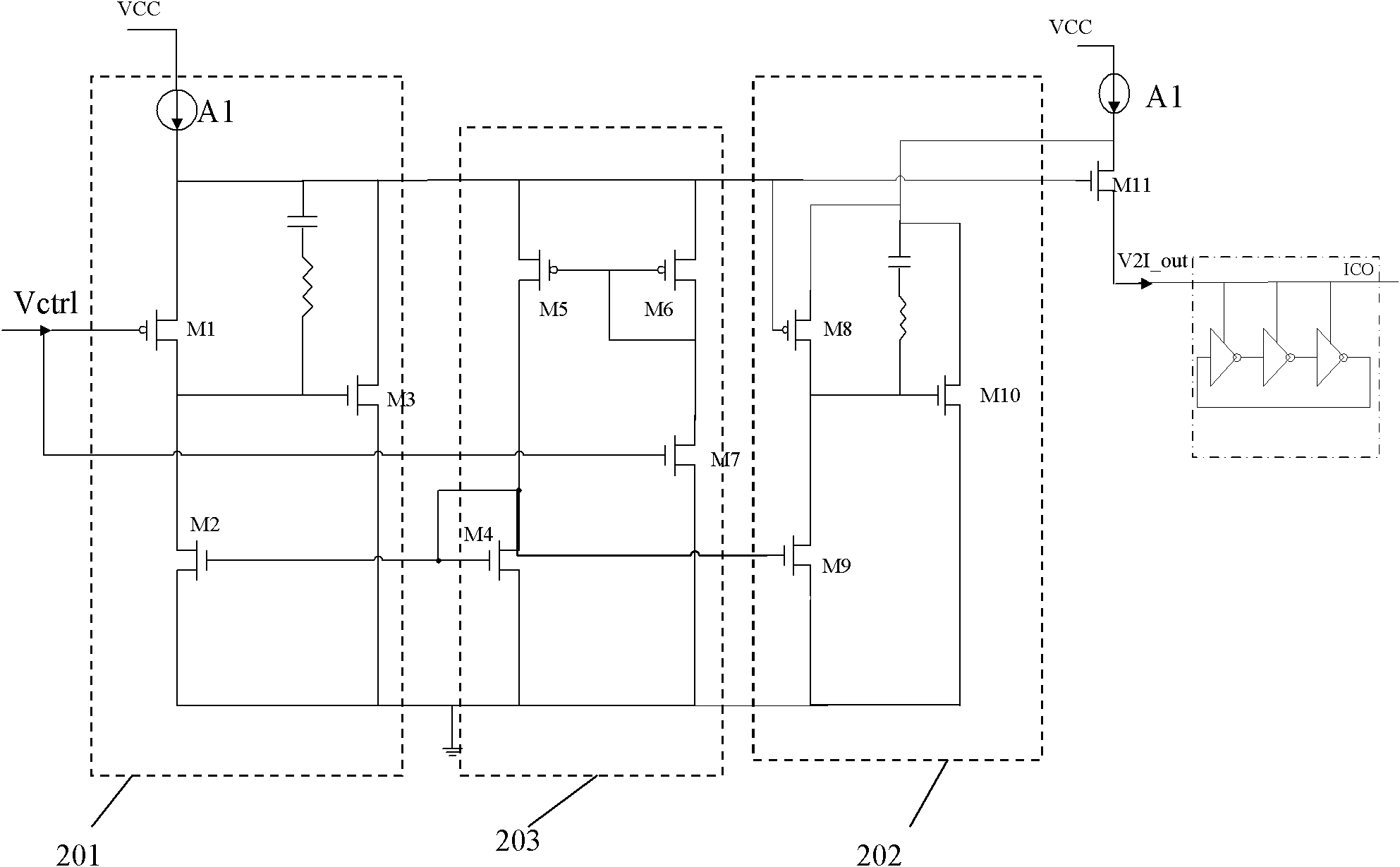
[0021] image 3 It is a circuit structure diagram of a preferred embodiment of a voltage-current converter of the present invention. Such as image 3 As shown, in a preferred embodiment of the present invention, the voltage-current converter of the present invention is used in a voltage-controlled oscillator (VCO), which at least includes: a first super source follower 201, a second super ...


PUM


Abstract

The invention discloses a voltage-to-current converter. The voltage-to-current converter comprises a first super source follower, a second super source follower and a current mirror image circuit. In the converter, output resistance is reduced by combining the two super source followers with the current mirror image circuit, and current is fed back to the super source followers to stabilize the super source followers through the current mirror image circuit to realize low impedance of an output end of the voltage-to-current converter; thus extremely high power supply rejection ratio can be obtained and good suppression effect on power noise can be achieved. The two super source followers are adopted to reduce the output voltage of the voltage-to-current converter and keep the output voltage close to input control voltage, so output of the converter can act on a current controlled oscillator of a metallic oxide semiconductor field effect transistor (MOSFET) device using low working voltage to improve the frequency of a voltage controlled oscillator.

Description

technical field [0001] The present invention relates to a voltage-current converter, in particular to a voltage-current converter for a voltage-controlled oscillator. Background technique [0002] As is well known in the art, a voltage-to-current converter is used to convert an input voltage into an output current proportional thereto. For example, a voltage-current converter is usually used in a voltage-controlled oscillator (generally abbreviated as VCO) in a phase-locked loop circuit. [0003] Traditional voltage-to-current conversion circuits usually use an NMOS transistor and a current mirror 10 to realize voltage-to-current conversion, such as figure 1 As shown, according to its working principle, the output current I2=I1 of the voltage-current converter, where I1 is the leakage current of the NMOS transistor M8, I1=V G, and V is the input voltage Vctrl of the voltage-current converter, G is the transconductance of the N-type MOS transistor M8, thereby realizing the ...

Claims


Application Information

Patent Timeline
Patent Type & Authority Applications(China)
IPC IPC(8): H03L7/099
Inventor 任铮胡少坚周伟唐逸
Owner SHANGHAI INTEGRATED CIRCUIT RES & DEV CENT
Why Eureka
Try Eureka