
Overcurrent detection for droplet ejectors

An injector and circuit technology, applied in printing, printing devices, etc., can solve problems such as inoperability and damage to ink nozzles, and achieve the effect of preventing indirect damage

Active Publication Date: 2013-10-09
FUJIFILM CORP
View PDF6 Cites 0 Cited by
  • Summary
  • Abstract
  • Description
  • Claims
  • Application Information

AI Technical Summary

Problems solved by technology

When an overcurrent condition does occur, multiple ink nozzles are damaged and cannot function

Method used


Image

  • Overcurrent detection for droplet ejectors
  • Overcurrent detection for droplet ejectors
  • Overcurrent detection for droplet ejectors

Examples


Embodiment Construction

[0018] Although an ink-based printer system is described below, the concepts are also generally applicable to other microelectromechanical systems (MEMS-based) devices that include driven piezoelectric layers, and are particularly applicable to fluid ejection systems that eject fluid.

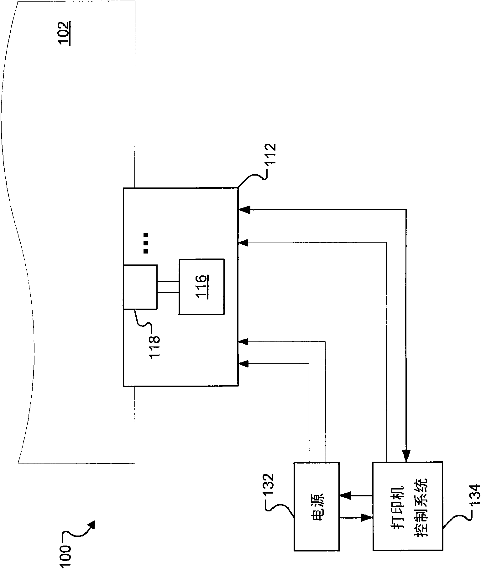
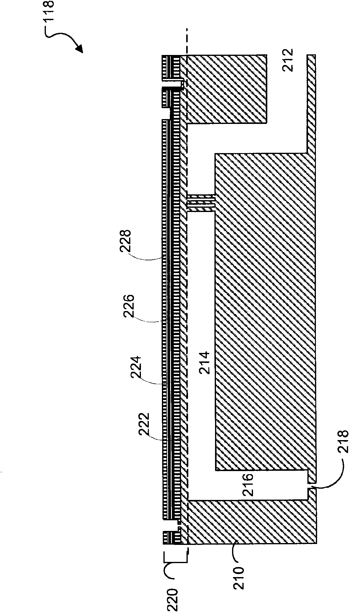
[0019] figure 1 A schematic plan view of an exemplary fluid ejection system, such as printer unit 100, is shown. Printer unit 100 includes one or more fluid ejectors, such as one or more printheads 112 . The printhead 112 may deposit a fluid material (eg, ink) onto a receiving surface 102 (eg, a recording medium, such as paper, or a substrate undergoing integrated circuit fabrication). In some embodiments, the printhead 112 and / or the receiving surface 102 can move or translate relative to each other such that fluid can be deposited at different locations on the receiving surface 102 . For example, the flat and flexible receiving surface 102 (eg, paper) can be translated by one or more roller...


PUM


Abstract

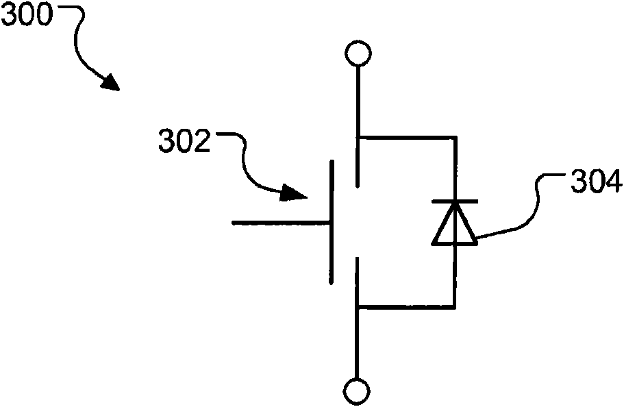
An apparatus, method, and a fluid ejection system for detecting electrical shorts in piezoelectric printheads are described. An apparatus includes a piezoelectric actuator, a transistor whose drain is connected to the piezoelectric actuator, a diode that is connected to a source and the drain of the transistor, a detection circuit configured to detect whether a voltage at the drain of the transistor is above a predefined voltage, and a disabling circuit configured to turning off the transistor in response to detecting that voltage at the drain of the transistor is above the predefined voltage.

Description

technical field [0001] The present invention generally relates to fluid ejectors, such as inkjet printheads. Background technique [0002] An inkjet printhead herein may have a plurality of piezo-controlled ink ejectors, each including a suction chamber connected to a nozzle. The piezoelectric material can be electrically coupled to an application specific integrated circuit (ASIC). The ASIC drives the piezoelectric material, which actuates the pumping chamber and ejects ink from the associated nozzle. [0003] Piezoelectrically controlled ink nozzles and ASICs can be packaged in a relatively small area. Due to small areas and defects or degradation of the electrical paths in the ASIC and connections between the ASIC and the piezoelectric material, short circuits and thus overcurrent conditions can occur. When an overcurrent condition does occur, multiple ink nozzles are damaged and cannot function. Contents of the invention [0004] In general, an aspect of the subjec...

Claims


Application Information

Patent Timeline
Patent Type & Authority Patents(China)
IPC IPC(8): B41J29/38
CPCB41J2/0451B41J2/04541B41J2/04581B41J29/393B41J2/04555
Inventor 保罗·A·霍伊辛顿迪恩·A·加德纳
Owner FUJIFILM CORP
Learn More