
High-precision diagnostic equipment collimation method and device thereof

A technology of diagnostic equipment and aiming device, applied in the directions of diagnosis, diagnostic recording/measurement, medical science, etc., can solve the problems of limited space, low aiming accuracy, complex aiming device, etc., and achieve the effect of convenient application and high-precision aiming

Inactive Publication Date: 2011-05-04
XI'AN INST OF OPTICS & FINE MECHANICS - CHINESE ACAD OF SCI
View PDF2 Cites 8 Cited by
  • Summary
  • Abstract
  • Description
  • Claims
  • Application Information

AI Technical Summary

Problems solved by technology

[0006] The present invention aims to provide a method for aiming high-precision diagnostic equipment to solve the problems of low aiming accuracy, complicated aiming devices, and limited space in traditional aiming methods

Method used


Image

  • High-precision diagnostic equipment collimation method and device thereof
  • High-precision diagnostic equipment collimation method and device thereof
  • High-precision diagnostic equipment collimation method and device thereof

Examples


Embodiment Construction

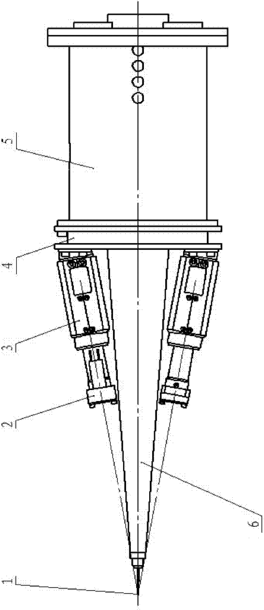
[0031] The invention adopts the principle of optical imaging CCD intersection measurement, images the target point on the CCD, interprets the images of the two CCDs, and obtains the off-center position from the intersection. structure see image 3 As shown, it is composed of lens, CCD and aiming section. The purpose of the aiming joint is to connect it with diagnostic equipment. When the CCD intersection measurement point coincides with the target point, it means that the diagnostic equipment is strictly pointing to the target point.

[0032] 1) CCD intersection measurement model

[0033] Such as Figure 4 As shown, two CCD cameras are respectively installed at two points of the aiming section, and the line connecting the two points is the baseline S. Take one point as the coordinate origin O, the baseline S as the X axis, the pitch as the Y axis, and the azimuth as the Z axis.

[0034] Within the field of view, when the diagnostic equipment is not aimed, the coordinates ...


PUM


Abstract

The invention provides a high-precision diagnostic equipment collimation method and a device thereof, and aims to solve the problems of low collimation precision, complex collimation device and limited space in the traditional collimation method. The method comprises the following steps: imaging a target point on two sets of CCDs (Charge Coupled Devices) in an optical imaging convergence measurement mode; interpreting the two sets of CCD images to obtain CCD convergence measuring point coordinates; when the CCD convergence measuring point coordinates coincide with the initialization-given target point coordinates, indicating that the diagnostic equipment strictly points to the target point, which means collimated; and when the CCD convergence measuring point coordinates do not coincide with the initialization-given target point coordinates, adjusting the degree of freedom of the diagnostic equipment collimation structure in three directions according to the CCD convergence measurement model established during initialization until the CCD convergence measuring point coincides with the target point. The invention has high collimation precision up to 5-10 mu m; and the system can judge whether the diagnostic equipment is collimated without a target monitoring system for observing the collimation condition of the collimated target point, so that the invention is convenient for use.

Description

technical field [0001] The invention relates to a method and device for aiming high-precision diagnostic equipment. Background technique [0002] In order to ensure that the diagnostic equipment is aimed at the target point, the diagnostic equipment has an aiming device. Different aiming methods determine the accuracy and performance of aiming. Common aiming methods mainly include: single laser beam aiming, double laser beam intersection aiming. [0003] A single laser beam aiming method such as figure 1 As shown, the laser beam is coaxial with the optical axis of the optical system. When the laser beam points to the target point, it means that the optical axis of the measurement system points to the target. This method does not occupy the external space, but it needs to occupy the light hole, so the application is limited. [0004] Double laser beam intersection and aiming: the aiming is completed by two laser focusing and emitting devices through intersection. The las...

Claims


Application Information

Patent Timeline
IPC IPC(8): A61B19/00A61B5/00
Inventor 何俊华张敏闫亚东王维韦明智谢正茂
Owner XI'AN INST OF OPTICS & FINE MECHANICS - CHINESE ACAD OF SCI
Learn More