Deployable reflecting surface device under traction drive of rope

A traction drive, reflective surface technology, applied in the field of machinery, can solve the problems of difficult deployment speed and stability, low storage rate, complex structure, etc., achieve the advantages of profile precision adjustment, overcome excessive deployment speed, and have wide application prospects. Effect

Inactive Publication Date: 2011-05-04
XIDIAN UNIV
View PDF5 Cites 15 Cited by
  • Summary
  • Abstract
  • Description
  • Claims
  • Application Information

AI Technical Summary

Problems solved by technology

This structural scheme has two major defects: one is the use of a Z-shaped folded truss rib structure, the structure is complex, and the storage rate in the radial and height directions is not high, that is, the storage rate in the height direction is less than 2, and its quality and corresponding surface density are also low. It is not low; the second is that the circumference is pulled by a flexible rope, it is difficult to ensure the desired regular hexagonal surface accuracy, and the aperture efficiency is very low if a circular reflective surface is to be formed
[0004] 1) When many torsion springs work at the same time, the reliability will be reduced, and the torsion springs increase the weight of the structure;
[0005] 2) When the binding is released, the energy of the torsion spring is released instantly, which makes it difficult to effectively control the deployment speed and stability, and also adversely affects the locking process

Method used


Image

  • Deployable reflecting surface device under traction drive of rope
  • Deployable reflecting surface device under traction drive of rope
  • Deployable reflecting surface device under traction drive of rope

Examples


Embodiment Construction

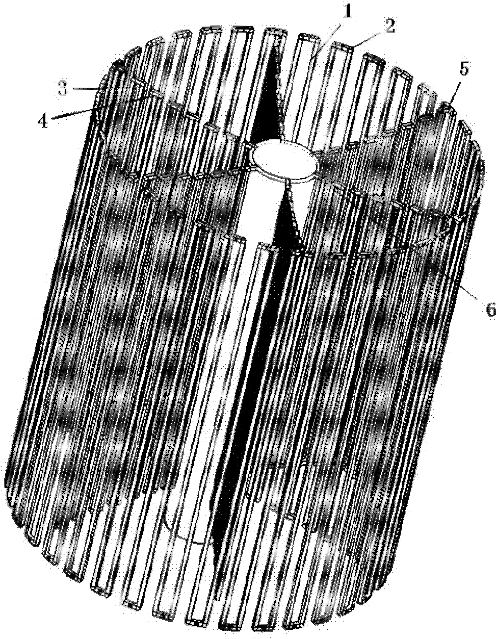
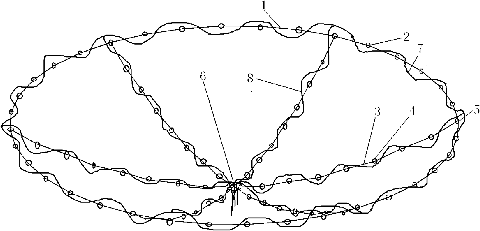
[0030] Such as figure 1 with figure 2 As shown, the present invention includes: foldable ring rod 1, ring rod connection joint 2, foldable rib rod 3, rib rod connection joint 4, ring rib connection joint 5, rib cylinder connection joint 6, hoop traction rope 7, diameter To the traction rope 8. The foldable ring rod 1 and the foldable rib rod 3, the ring rod connection joint 2, the rib rod connection joint 4, the ring rib connection joint 5, the rib cylinder connection joint 6, and the radial traction rope 8 are plural numbers, the specific numbers and geometric dimensions According to the diameter of the unfolding reflective surface, this embodiment adopts six rib structures to support the unfolding ring, but it is not limited to six. These foldable ring rods and foldable rib rods are straight rods to obtain a high storage rate, and the section is hollow to facilitate the smooth passage of the traction rope, while also reducing the mass of the entire device.

[0031] When ...


PUM


Abstract

The invention discloses a deployable reflecting surface device under the traction drive of a rope. The device disclosed by the invention mainly aims to overcome the defects of the existing reflecting surface device that the unfolding speed is too fast and the reflecting surface device is difficult to control and has low reliability. The device comprises a group of hauling ropes, a folding eye bar, a folding rib rod and a plurality of connecting joints, wherein a sealed circumferential hauling rope (7) penetrates through a ring structure formed by connecting an eye bar (1) and an eye bar connecting joint (2); radial hauling ropes (8) penetrate through a rib structure formed by connecting a rib rod (3) and a rib rod connecting joint (4); one end of the rib structure and one end of each radial hauling rope are connected with the ring structure and the circumferential hauling rope through a ring-rib connecting joint (5); the other end of the rib structure is connected with a rib tube connecting joint (6); and the radial hauling rope are combined to form a hauling rope at the rib tube connecting joint, and the hauling rope is connected with an external motor. The invention has the advantages of low surface density, steady and reliable unfolding process and adjustable profile precision and can be used as a reflector or converger to be arranged in space or on the ground.

Description

technical field [0001] The invention belongs to the technical field of machinery, and in particular relates to an expandable reflecting surface device driven by rope traction, which is mainly used in driving large-scale expandable mechanisms in space or on the ground. Background technique [0002] The rapid development of space technology and the continuous expansion of aerospace applications have put forward higher and higher requirements for space structures. Limited by the size and carrying capacity of launch vehicles, space deployable structures have been increasingly favored as a new type of structure. Wider applications, such as large deployable antennas, solar panels, extension arms, etc. The high cost and high risk of aerospace applications, and the significant difference between the ground development environment and the space working environment make the design of large-scale deployable devices one of the key technologies for aerospace applications. Large-scale de...

Claims


Application Information

Patent Timeline
Patent Type & Authority Applications(China)
IPC IPC(8): B64G1/42H01Q1/08H01Q15/14G02B7/183
Inventor 郑飞陈梅赵林燕李琦郝海明魏田何宏满
Owner XIDIAN UNIV
Why Eureka
Try Eureka