Working station for transaction system, and working method and material loading and unloading methods thereof

A transaction system and workstation technology, applied in the field of pipeline transmission system, can solve the problems of affecting transaction time, complicated control, large friction, etc., and achieve the effect of convenient operation.

Active Publication Date: 2011-05-04
BEIJING RINRONG TECH
View PDF4 Cites 2 Cited by
  • Summary
  • Abstract
  • Description
  • Claims
  • Application Information

AI Technical Summary

Problems solved by technology

[0007] The openings on the side walls of the vertical pipes are often set relatively narrow. If the openings are too large, it is not conducive to the conveyor entering the transmission pipe and wastes materials. Put the conveyor into the workstation from the opening or put the conveyor from the opening It is very inconvenient to take it out, and sometimes the operator's hands will be scratched; and for unfamiliar customers, they will not be able to operate (because the transmitter must be put into the mouth and the transmitter must be sent up for a section to the transmission In the pipeline, when the transmitter is dropped on the platform, the transmitter should be coaxial with the transmission pipeline, so that the workstation will not get the transmitter stuck in the transmission pipeline port when sending the transmitter; it is not only complicated but also easy to operate when putting the transmitter in. It takes a long time, because it needs manual operation to ensure that the transmitter is placed), and training is required, which affects the use and popularization of the equipment
[0008] And there is also an existing one that controls the opening and closing of the door of the valve as a sliding track movement, with long moving distance and large friction force, high manufacturing cost and low opening efficiency; complicated control; long opening time; affecting the transaction time

Method used


Image

  • Working station for transaction system, and working method and material loading and unloading methods thereof
  • Working station for transaction system, and working method and material loading and unloading methods thereof
  • Working station for transaction system, and working method and material loading and unloading methods thereof

Examples


Embodiment 1

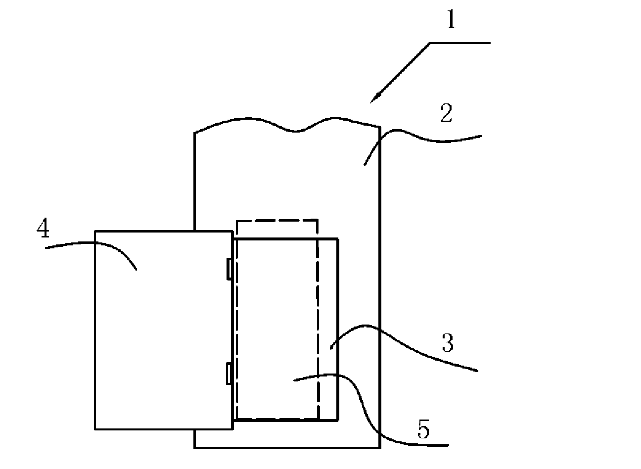
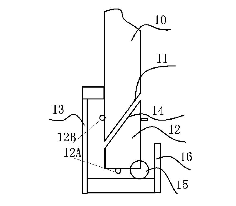
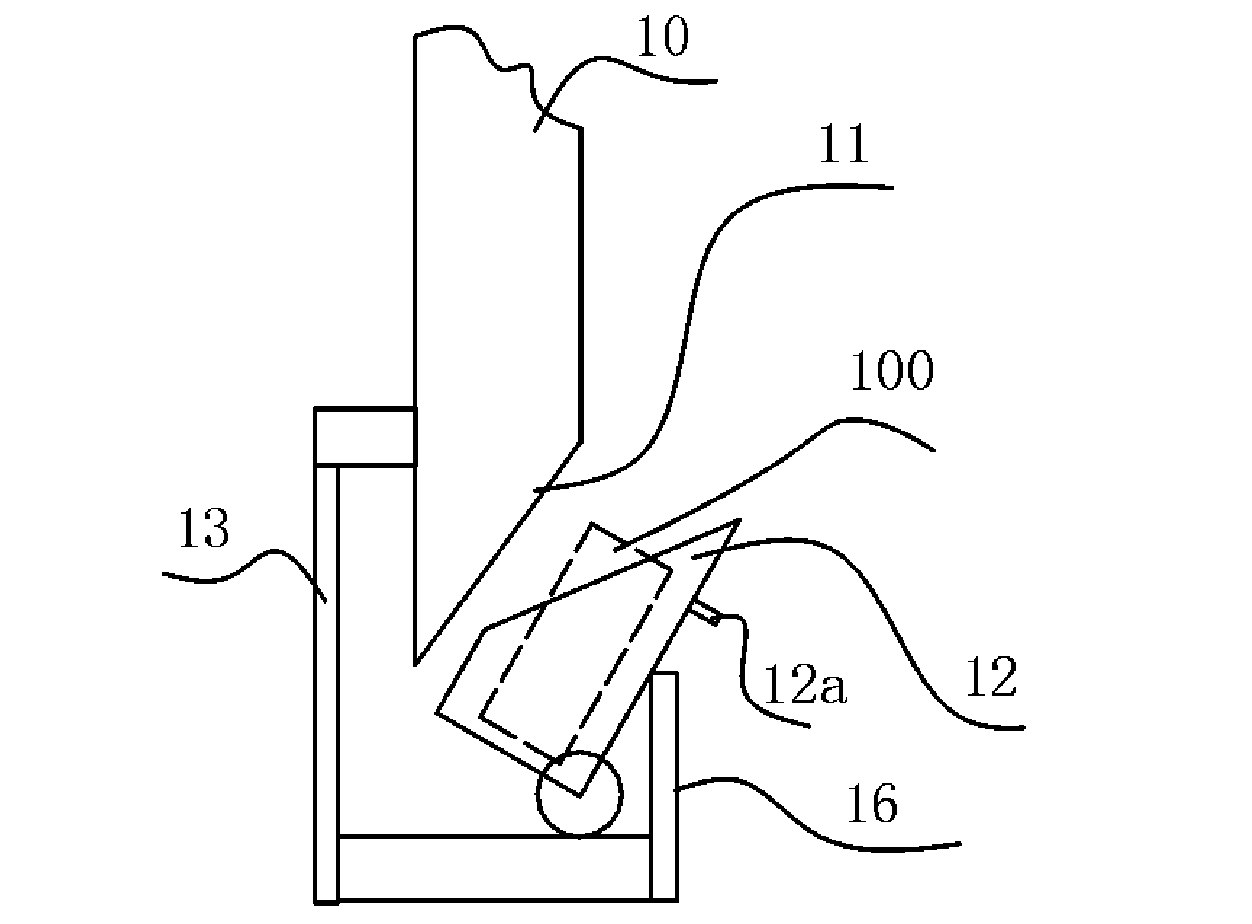
[0136] Such as figure 2 , image 3 As shown, the trading system workstation of the embodiment of the present invention includes a vertical pipeline 10, a port 11 is provided at the lower end of the vertical pipeline 10, and a container 12 is pivotally connected to the port 11 at the lower end of the vertical pipeline. The container is pivotally connected to the frame body 13 through a pivot shaft 15, the vertical pipe 10 is fixed on the frame body 13, the upper end of the container has an opening 14, and the opening 14 at the upper end of the container is connected to the frame body 13. The port 11 at the lower end of the vertical pipe is adapted, wherein the port 11 at the lower end of the vertical pipe is an inclined port; the container 12 is a pipe section with a closed bottom and an inclined opening at the upper end, and the inside of the pipe section There is an accommodating space for containing an object 100 (such as a transmitter) to be sent or received; the containe...

Embodiment 2

[0146] In order to realize automatic control and enable the container to be opened automatically, on the basis of the first embodiment, in this embodiment, the workstation further includes a driving mechanism for driving the container to turn over and reset.

[0147]In this embodiment, the pivot shaft is fixed at the bottom of the container; the driving mechanism includes a power device (not shown) fixedly connected to the pivot shaft. The power device is a stepping motor, and the precise control of the rotation angle of the container can be realized by adopting the stepping motor. The power unit may also include a motor and a gear transmission mechanism connected to the motor.

[0148] The drive mechanism drives the receptacle to flip open, presenting the opening of the receptacle in front of the operator, which not only facilitates the operation, but also serves as a reminder to the operator, making the entire operation appear more humane.

Embodiment 3

[0150] When the workstation receives the transmitter, the transmitter falls by gravity along a transfer conduit connected to the vertical conduit of the workstation, thereby creating a positive air pressure inside the workstation. In order to prevent the container 12 pivotally connected to the port 11 at the lower end of the vertical pipe from accidentally rotating and opening under the action of the positive air pressure, this embodiment is based on the above-mentioned embodiments. The system workstation also includes means for maintaining said receptacle closed.

[0151] Such as Figure 5 , Figure 6 and Figure 7 As shown, in the embodiment of the present invention, the locking device for keeping the container in a closed state is a lock device 214 installed at the closing position between the container and the pipeline. The lock device includes a lock slot provided on the vertical pipe 11 and a lock tongue 214 provided on the container 12, when the container 12 is close...


PUM


Abstract

The invention discloses a working station for a transaction system, and a working method and material loading and unloading methods thereof, which relate to the field of pipe transmission and are invented for making it convenient to load and unload materials in the working station for a pneumatic pipe transmission system. The working station for the transaction system comprises a conveying pipe, and is characterized in that: the port on one end of the pipe is hinged with a container or elastically connected with the container; the container is symmetric about a hinge or an elastic element, or the container is centrosymmetric about a hinged point or the elastic element; and one end of the container has an opening, and the opening of the container is matched with the port of the pipe.

Description

technical field [0001] The present invention relates to the field of pipeline transmission systems, and in particular to a pneumatic transmission pipeline system workstation and a method for putting in or taking out items; it is especially suitable for systems for conducting transactions between customers and service providers, which transactions may involve banking, Entertainment venues, lottery, betting hypermarkets, bill payment, dispensing, post office business or transaction systems for other business services. Background technique [0002] Pneumatic pipeline transmission system is a modern and fast logistics transportation tool. The pneumatic pipeline transmission system is used in hospitals, banks, office buildings, supermarkets, production workshops, laboratories and other places where a large number of items need to be transported every day. It can transmit medical records, medical certificates, medicines, laboratory tests, bills, cash, documents and any other item...

Claims


Application Information

Patent Timeline
Patent Type & Authority Applications(China)
IPC IPC(8): B65G51/04B65G51/18B65G51/26B65G51/28B65G51/30
CPCB65G51/04B65G51/06B65G51/18B65G51/28B65G51/30
Inventor 陆洪瑞
Owner BEIJING RINRONG TECH
Why Eureka
Try Eureka