Design method of automatic moving feeding frame of base material longitudinal cutting device

A technology of automatic movement and design method, applied in the direction of winding strips, thin material handling, sending objects, etc., can solve problems such as instability, cutting speed cannot be increased, and cannot work normally

Active Publication Date: 2011-05-04
XIAN XINDA MACHINERY
View PDF8 Cites 14 Cited by
  • Summary
  • Abstract
  • Description
  • Claims
  • Application Information

AI Technical Summary

Problems solved by technology

[0002] In the existing longitudinal slitting machine, the traditional unwinding frame is fixed. During the slitting process, the diameter of the base material of the unwinding shaft decreases continuously, so that the distance between the surface of the base material of the unwinding shaft and the unwinding guide roller c

Method used


Image

  • Design method of automatic moving feeding frame of base material longitudinal cutting device
  • Design method of automatic moving feeding frame of base material longitudinal cutting device

Examples


Embodiment 1

[0017] Embodiment 1 The automatic moving discharge rack of the substrate longitudinal slitting equipment is characterized in that it includes a sensor, an automatic adjustment device, a power mechanism, a transmission mechanism, and an adjustment mechanism; the sensor is electrically connected to the automatic adjustment device, and the automatic adjustment device It is electrically connected with the power mechanism, and the power mechanism is connected to the moving mechanism through the transmission mechanism, and the moving mechanism is fixedly connected with the discharge rack 1 . It uses the electrical automatic control system to transmit the signal to the servo motor to drive the precision transmission to drive the unwinding frame 1 to move automatically to realize the constant distance between the surface of the unwinding shaft substrate and the unwinding guide roller, to ensure constant tension of the cutting substrate 3, and to improve Slitting speed.

[0018] In an ...

Embodiment 2

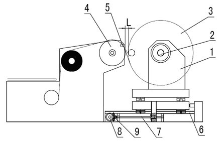
[0019] Example 2 as figure 1 As shown, the detection photoelectric head 5 is fixed on the unwinding guide roller 4? ? ,

[0020] The detection photoelectric head 5 is electrically connected to the variable-range automatic logic controller PLC, and the variable-range automatic logic controller PLC is electrically connected to the transmission servo motor 8. The servo motor 8 is connected to the ball screw 7 through the bevel gear 9, and the ball screw Pay 7 to be connected with sliding track 6 transmissions by screw nut. The nut of the ball screw 7 is fixedly connected with the sliding track bracket. There is a pulley at the bottom of the sliding track bracket. The pulley slides on the sliding track 6 to drive the fixed discharge rack 1 and the unwinding air shaft 2 on the sliding track bracket. Cut substrate 3 moves.

[0021] When unwinding, through the detection of the photoelectric head 5, the electrical signal is transmitted to the PLC to compare with the original set v...


PUM


Abstract

The invention relates to a base material longitudinal cutting device, particularly to a design method of an automatic moving feeding frame of a base material longitudinal cutting device, characterized by comprising a sensor, an automatic adjusting device, a power mechanism, a transmission mechanism and an adjusting mechanism; the sensor is electrically connected with the automatic adjusting device, the automatic adjusting device is electrically connected with the power mechanism, the power mechanism is in transmission connection with a moving mechanism through the transmission mechanism, and the moving mechanism is fixedly connected with the feeding frame. The automatic moving feeding frame of the base material longitudinal cutting device can ensure constant distance between an unwinding shaft base material surface and an unwinding guide rail, so that tension is steady, and cutting speed is improved.

Description

technical field [0001] The invention relates to a base material longitudinal slitting device, in particular to an automatic moving unloading rack of the base material longitudinal slitting device. Background technique [0002] In the existing longitudinal slitting machine, the traditional unwinding frame is fixed. During the slitting process, the diameter of the base material of the unwinding shaft decreases continuously, so that the distance between the surface of the base material of the unwinding shaft and the unwinding guide roller continues to increase. , the L distance in the figure, that is, the suspending length of the substrate is getting longer and longer, the airflow generated during the high-speed unwinding process makes the substrate shake and the tension is unstable, and it cannot work normally, so that the slitting speed cannot be increased. Contents of the invention [0003] The purpose of the present invention is to provide a design method for the automati...

Claims


Application Information

Patent Timeline
IPC IPC(8): B65H35/02B65H23/182
Inventor 曹新民
Owner XIAN XINDA MACHINERY
Why Eureka
Try Eureka