Non-leakage idling resistant centrifugal pump

A centrifugal pump, no leakage technology, applied in the direction of pumps, pump components, non-variable-capacity pumps, etc., can solve the problems of difficult use, inconvenient operation, poor sealing performance, etc., achieve simple design and application, better sealing effect, Stable and reliable performance

Active Publication Date: 2011-05-04
JIANGSU WUXIN PUMP IND CO LTD
View PDF0 Cites 5 Cited by
  • Summary
  • Abstract
  • Description
  • Claims
  • Application Information

AI Technical Summary

Problems solved by technology

If the medium contains particles of impurities, the sealing surface is likely to be solidified with impurities, uneven wear, and high temperature, which will accelerate the wear, make the sealing performance worse, more likely to leak, and shorten the service life of the whole pump prematurely; Insufficient liquid, material blockage, and dehydration will cause damage and burn to the mechanical seal, thus causing damage to other parts
In view of the above situation, various designers have come up with various and intricate seals to deal with, and installed various external circulation water cooling, internal circulation cooling and other devices to prolong the overall service life of the pump. The above are complicated to manufacture, difficult to use and difficult to operate Inconvenient and costly, in the end, the dehydration operation of the centrifugal pump and the manufacture of a durable centrifugal pump have not been really solved. Over time, the phenomenon of "running, popping, dripping, and leaking" often occurs

Method used


Image

  • Non-leakage idling resistant centrifugal pump
  • Non-leakage idling resistant centrifugal pump
  • Non-leakage idling resistant centrifugal pump

Examples


Embodiment Construction

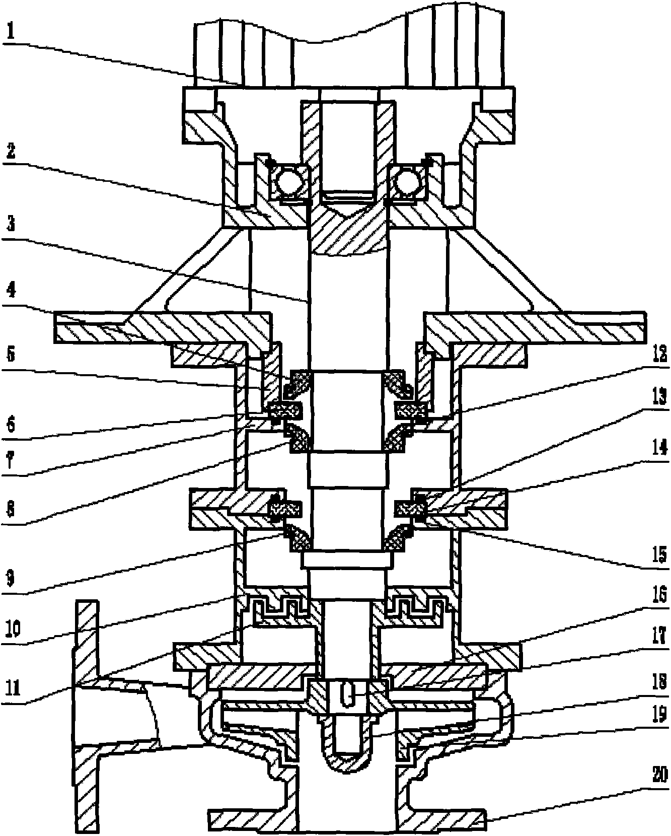
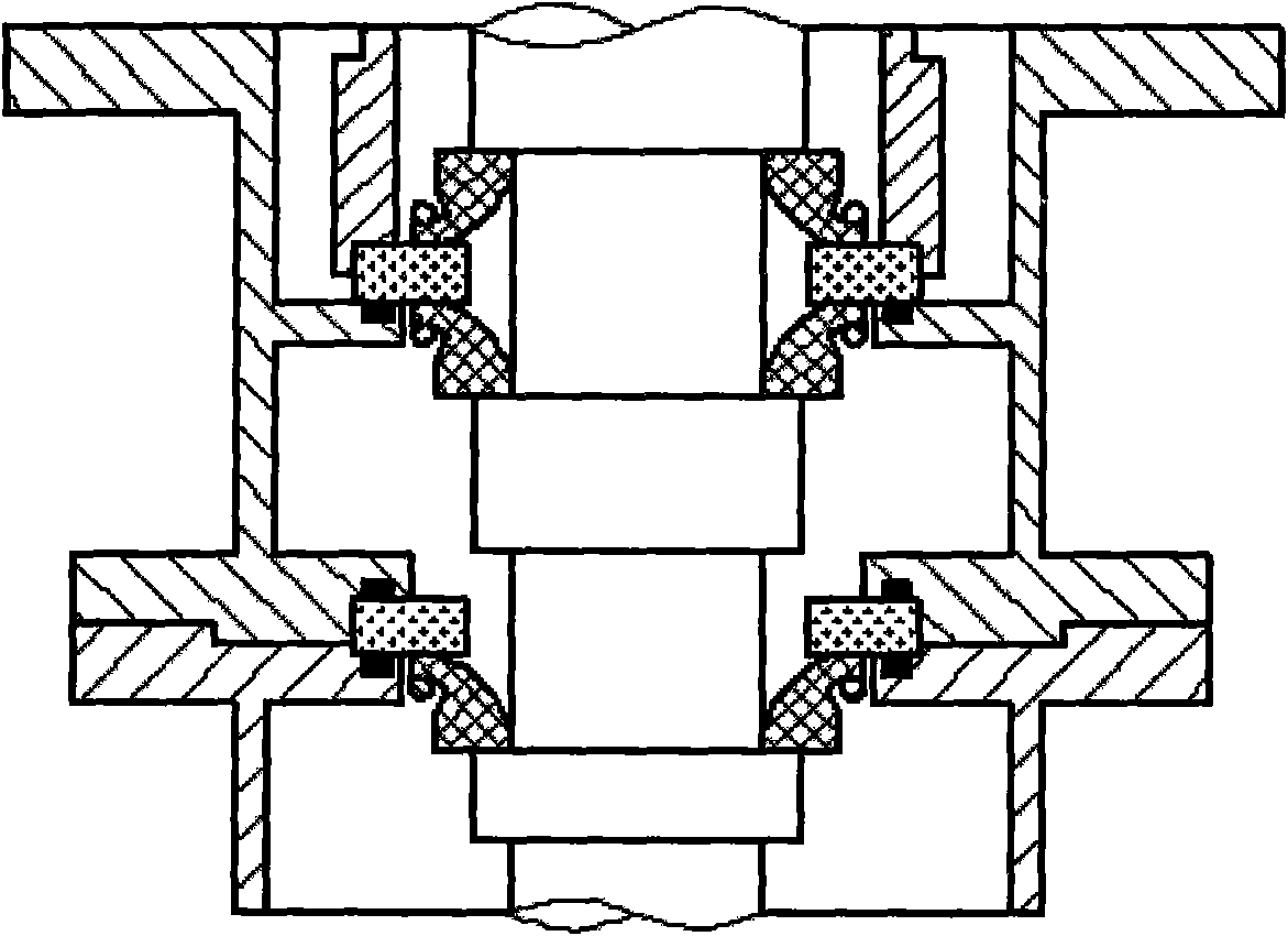
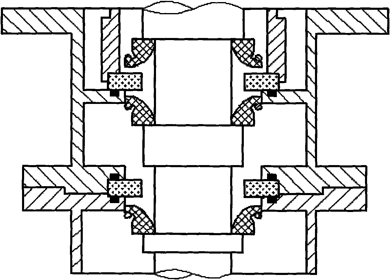
[0028]The non-leakage resistant idling centrifugal pump of the present invention will be further described through the following examples: (1) motor and (2) bracket, (7) middle tube (1) screws are fastened; (2) bracket compresses (5) static ring Seat, (6) Static ring I, (12) O-ring (1) embedded in grooved (7) middle cylinder (1); (4) Power centrifugal shaft seal ①, (8) Power centrifugal shaft seal ② , (9) power centrifugal shaft seal ③ is closely matched with (3) pump shaft; (7) middle cylinder (1) is connected with (10) middle cylinder (2), and (14) static ring II is embedded by (13)O Type rings (2), (15) O-rings (3) are embedded in (7) middle cylinder (1) and (10) middle cylinder (2) with grooves; (11) labyrinth or auxiliary impeller dynamic seal clearance fit Control; the bottom is equipped with (16) back cover, (17) key, (18) lock nut, (19) impeller, (20) pump body. When the pump rotates, all parts closely matched with the pump shaft also move accordingly, the liquid in t...


PUM


Abstract

The invention relates to a non-leakage idling resistant centrifugal pump which is suitable for liquid delivery in various fields. The technical scheme and method scheme in the invention are as follows: the centrifugal pump is in a vertical type, a power centrifugal shaft seal fits and contacts with a static ring, the edge of the centrifugal shaft seal is provided with a weight block which can be detached during operation; when the pump operates, a labyrinth seal or an auxiliary impeller dynamic seal is used to seal the pump chamber; when the pump stops, the power centrifugal shaft seal closely contacts with the static ring and the seal simultaneously, the liquid level difference is utilized and two shaft seal groups are used for sealing, thus the design is elaborate, the combination is ingenious, no barrier or leakage exist during idling and the pump has no special requirement on the installation site; and the electric motor is matched with an oversize bearing and the motor shaft and the pump shaft are in close fit through a hot jacket or a one-shaft structure, thus the performance of the pump is reliable and the energy consumption is low. The impeller and the pump shaft adopt keys and lock nuts, thus preventing the pump counter rotational impeller from falling off. The centrifugal pump in the invention has the advantages of high efficiency, no leakage, idling resistance, low maintenance cost and long service life, is simple in operation, and is energy-saving, environment-friendly and the like.

Description

Technical field: [0001] The invention relates to a non-leakage idling-resistant centrifugal pump, which is widely used in the fields of electronics, electric power, chemical industry, steel, food, electroplating, environmental protection, fire protection, urban sewage, national defense and military industry, etc. Especially the use of vertical centrifugal pumps under the device involving particulate impurities in the medium, insufficient inlet liquid, easy flow of the medium, and dehydration is even more superior. Background technique: [0002] As a related technology of the non-leakage and idling-resistant centrifugal pump of the present invention, it is beneficial to the good operation of the delivery pump for chemical liquid (especially the medium contains particle impurities, the inlet liquid is insufficient, and the medium is easy to cut off and deliquify). Existing vertical and horizontal centrifugal pumps currently adopt a mechanical or packing seal. The static and dy...

Claims


Application Information

Patent Timeline
Patent Type & Authority Applications(China)
IPC IPC(8): F04D1/00F04D29/10
Inventor 刘铭
Owner JIANGSU WUXIN PUMP IND CO LTD
Why Eureka
Try Eureka