
Integrated slit cold head of U-shaped pulse tube refrigerating machine and manufacturing method

A technology of a pulse tube refrigerator and a manufacturing method, which are applied in refrigerators, gas cycle refrigerators, refrigeration and liquefaction, etc., can solve the problems of excessive dead volume, hindering practical application, increasing pressure drop loss, etc.

Inactive Publication Date: 2012-09-26
SHANGHAI INST OF TECHNICAL PHYSICS - CHINESE ACAD OF SCI
View PDF0 Cites 0 Cited by
  • Summary
  • Abstract
  • Description
  • Claims
  • Application Information

AI Technical Summary

Problems solved by technology

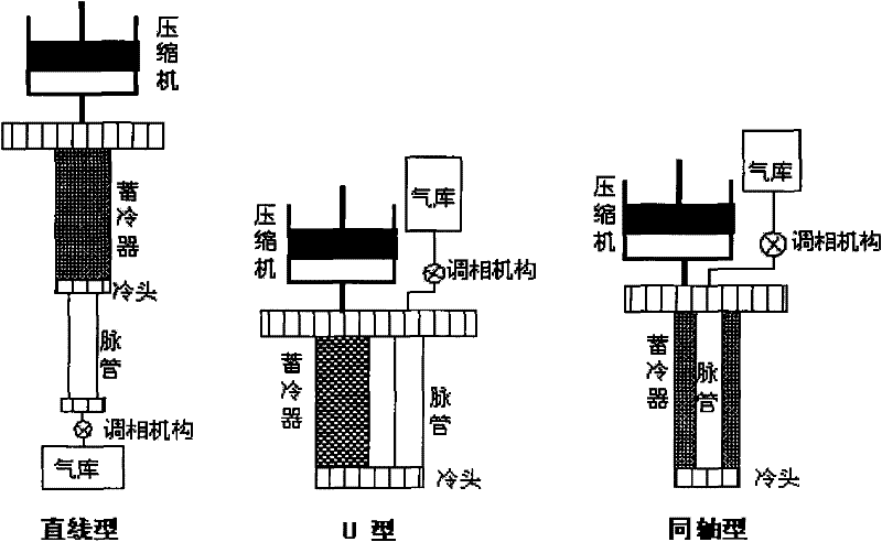
The three layout methods have their own advantages and disadvantages in practical application
[0011] 1) The cold head is divided into two, which is not conducive to coupling with the cooled device in practical applications;
[0012] 2) Larger resistance and cooling loss are brought about by connecting thin tubes;
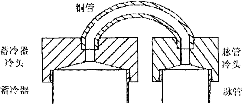
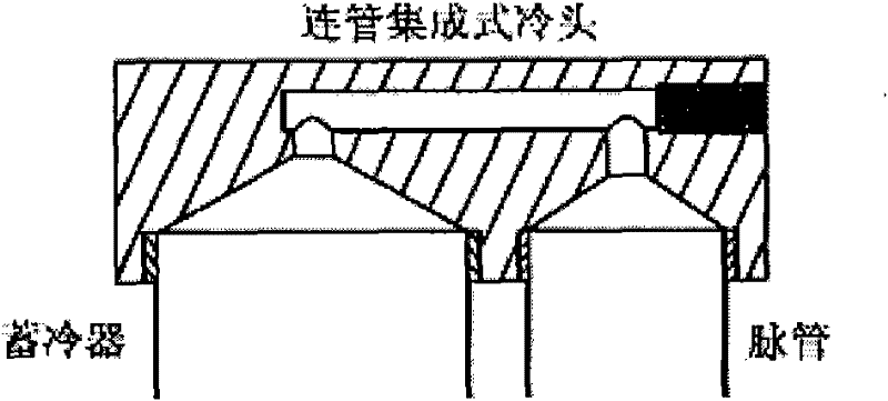
[0018] the above figure 2 and image 3 As shown in the conventional cold head, the multi-components of the cold end bring large contact thermal resistance, and introduce too large dead volume to increase the pressure drop loss; the insufficient heat exchange area of ​​the air flow makes the cooling capacity of the working gas not effectively transmission; its jet suppression and turbulence control difficulties increase its internal losses
The above-mentioned many factors lead to the decline of the overall performance of the refrigerator, which is one of the key factors affecting the actual refrigeration efficiency of the current U-shaped pulse tube refrigerator, and is also one of the important reasons hindering its practical application.

Method used


Image

  • Integrated slit cold head of U-shaped pulse tube refrigerating machine and manufacturing method
  • Integrated slit cold head of U-shaped pulse tube refrigerating machine and manufacturing method
  • Integrated slit cold head of U-shaped pulse tube refrigerating machine and manufacturing method

Examples


Embodiment Construction

[0036] The specific embodiment of the present invention is described in further detail below in conjunction with accompanying drawing:

[0037] The integrated slit cold head of the U-shaped pulse tube refrigerator of the present invention consists of two parts, the top cover 0 and the lower flange 13 . In order to enhance heat transfer, both parts are made of high thermal conductivity materials.

[0038] Such as Figure 4 Shown in (a): the lower part of the upper platform 1 of the top cover 0 at first protrudes a large boss 2 with a diameter slightly smaller than the upper platform 1, and then protrudes two outside the big boss 2 above the big boss 2. The cold storage side cylinder boss 3 and the pulse tube side cylinder boss 4 with tangent edges ensure that the outer diameters of the cold storage side cylinder boss 3 and the pulse tube side cylinder boss 4 are respectively in line with the cold storage 14 and the pulse tube side. The inner diameters of the tubes 15 are equa...


PUM


Abstract

The invention discloses an integrated slit cold head of a U-shaped pulse tube refrigerating machine and a manufacturing method. The cold head comprises two parts of a top cover and a lower flange, wherein two cylindrical lug bosses protrude below a big lug boss of the top cover, outer diameters of the two cylindrical lug bosses are respectively equal to inner diameters of a cold regenerator and apulse tube; the two lug bosses integrally cut and penetrate through a slit in parallel horizontally and uniformly; through insertion holes matched with the cylindrical lug bosses of the top cover arearranged on the lower flange, a sealing groove and a location groove matched with the big lug boss of the top cover are cut on the upper surface of the lower flange, the lower flange, the cold regenerator and the pulse tube are hermetically welded to form an assembly; the top cover and the lower flange not only can be connected by bolts to form a detachable split cold head, but also can be hermetically welded to form an integrated cold head. In the invention, the main functions of three parts of an efficient cold end heat exchanger, a pulse tube cold end gas director and a cold regenerator cold end gas distributor can be intensively realized in an integrated slit cold head structure, the overall performance of the U-shaped pulse tube refrigerating machine is enhanced.

Description

technical field [0001] The invention relates to a U-shaped pulse tube refrigerator, in particular to an integrated slit cold head on the U-shaped pulse tube refrigerator and a manufacturing method. Background technique [0002] The pulse tube refrigerator, which was proposed in the 1960s and developed rapidly since the mid-1980s, is a major innovation of the regenerative cryogenic refrigerator. It cancels the cold-end ejector widely used in Stirling or G-M machines, and replaces it with a completely passive empty pipe; it does not pass through the cold-end ejector, but realizes refrigeration through the operation of the hot-end phasing mechanism Desired pressure wave and mass flow phase difference. On the one hand, the complete cancellation of moving parts at the cold end enables the pulse tube refrigerator to achieve low vibration, low interference and no wear at the cold end; on the other hand, after a series of important improvements, its actual efficiency has also been ...

Claims


Application Information

Patent Timeline
Patent Type & Authority Patents(China)
IPC IPC(8): F25B9/14
CPCF25B2309/1408F25B9/145
Inventor 党海政李姗姗沈玮斌王立保杨开响吴亦农
Owner SHANGHAI INST OF TECHNICAL PHYSICS - CHINESE ACAD OF SCI
Learn More